Apparatus for filling charged aerosol cans

Inactive Publication Date: 2005-09-27
TUNGSTEN CAPITAL PARTNERS
View PDF8 Cites 23 Cited by
  • Summary
  • Abstract
  • Description
  • Claims
  • Application Information

AI Technical Summary

Benefits of technology

[0004]The invention provides an aerosol can filling device that is economical to produce, easy to use, and reliable in operation. The device includes an improved filling head with a valve seat construction that avoids critical surface machining in the injector valve seat area while affording a leak and blow back resistant valve operation. This improved valve operation is obtained through the use of a simple O-ring confined in an associated annular pocket. The O-ring forms the seat for a spring biased valve ball. The relatively soft nature of the O-ring, its surface geometry, and material characteristics, for yet unexplained reasons, effectively reduces the occurrence of leaks and blow back from a precharged aerosol can.
[0005]The filling device includes a simplifie

Problems solved by technology

Some devices have exhibited a tendency to allow propellant to leak back from a can and, in some cases, are susceptible to “blow back”.
In the latter case, where significant leakage flow occurs in an injector circuit, paint or other material in a reservoir on the filling device is uncontrollably expelled by propellant in the aerosol can.
These prior art can supporting/transporting mechanisms ty

Method used


Image

  • Apparatus for filling charged aerosol cans
  • Apparatus for filling charged aerosol cans
  • Apparatus for filling charged aerosol cans

Examples


Embodiment Construction

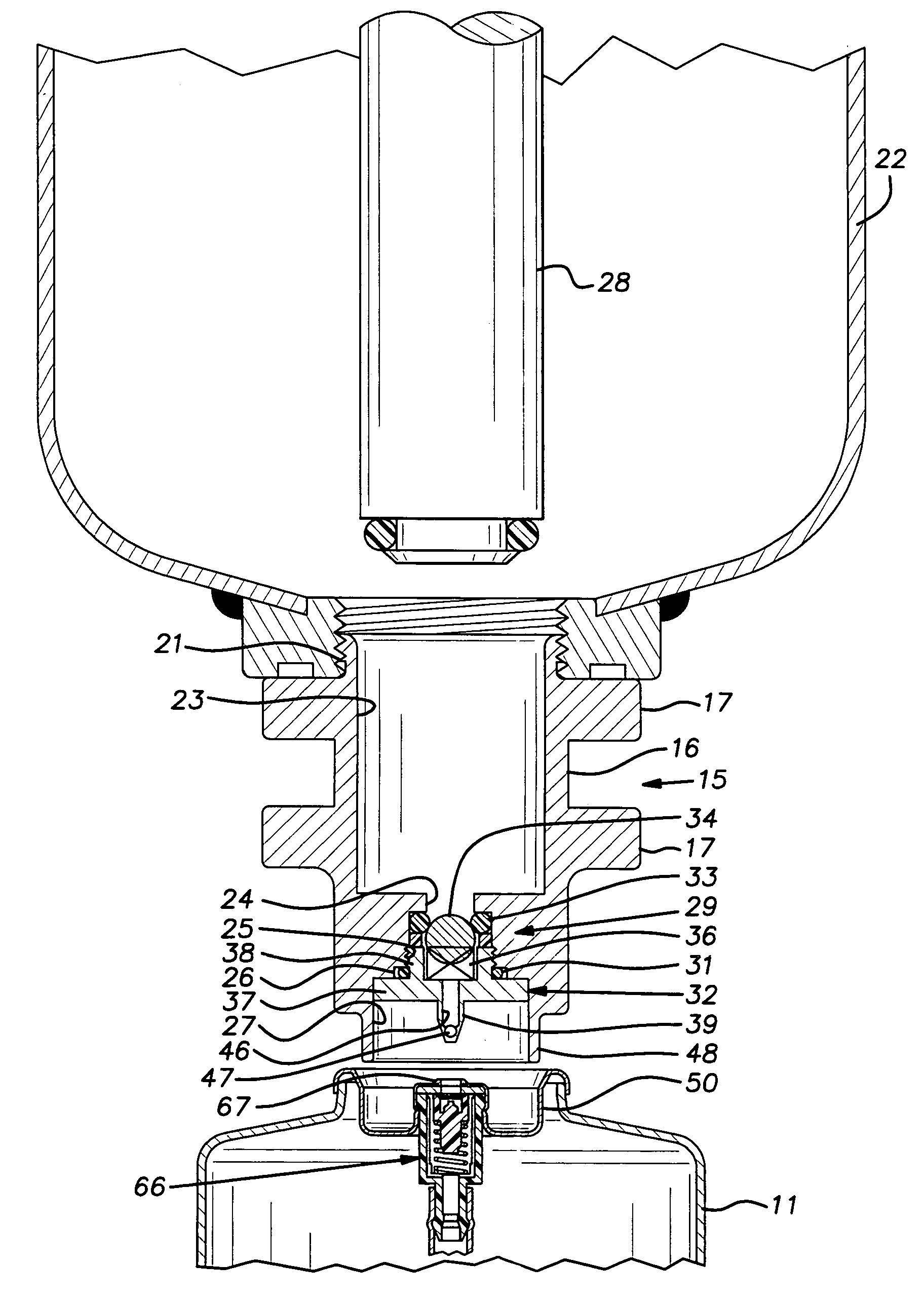
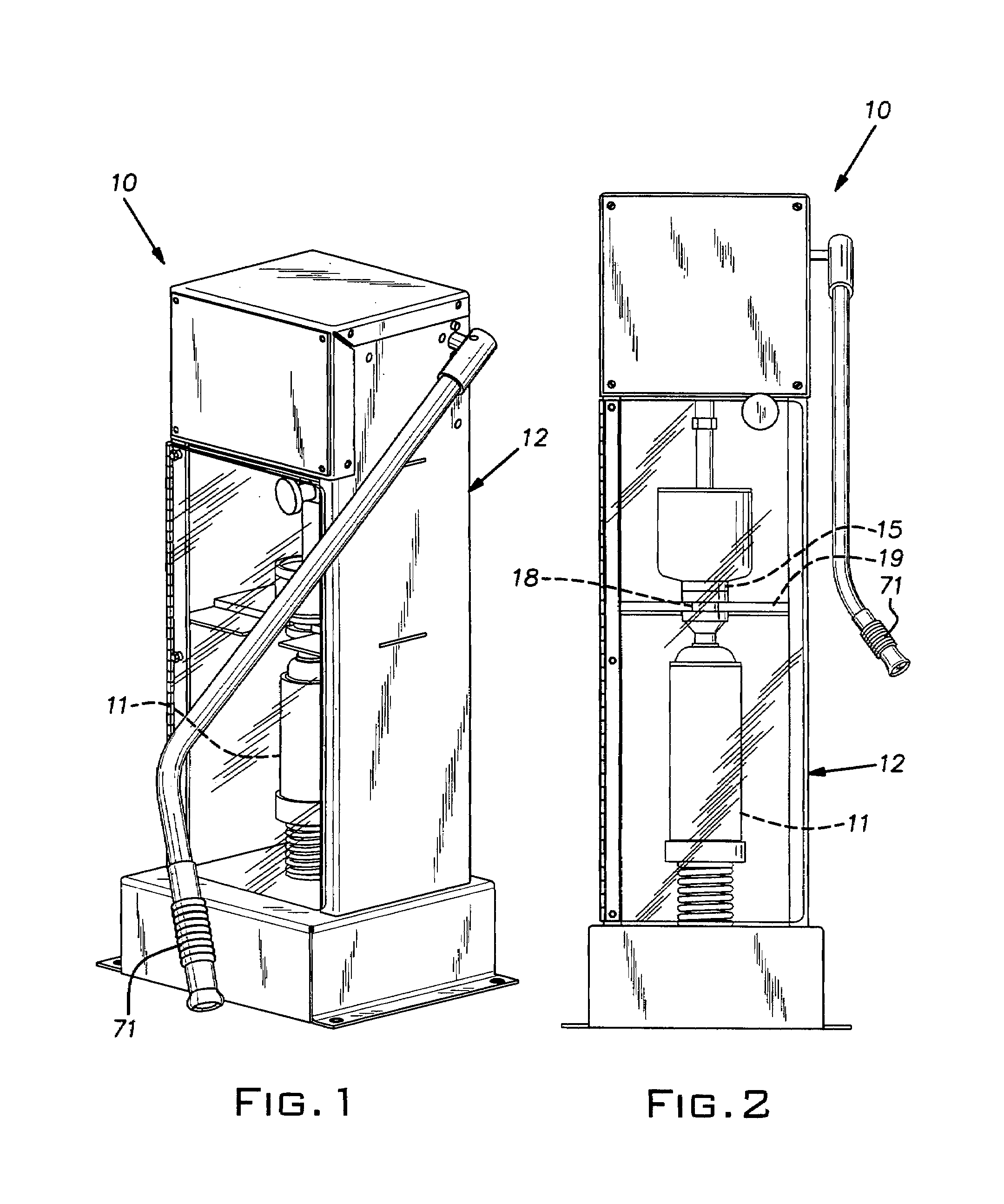
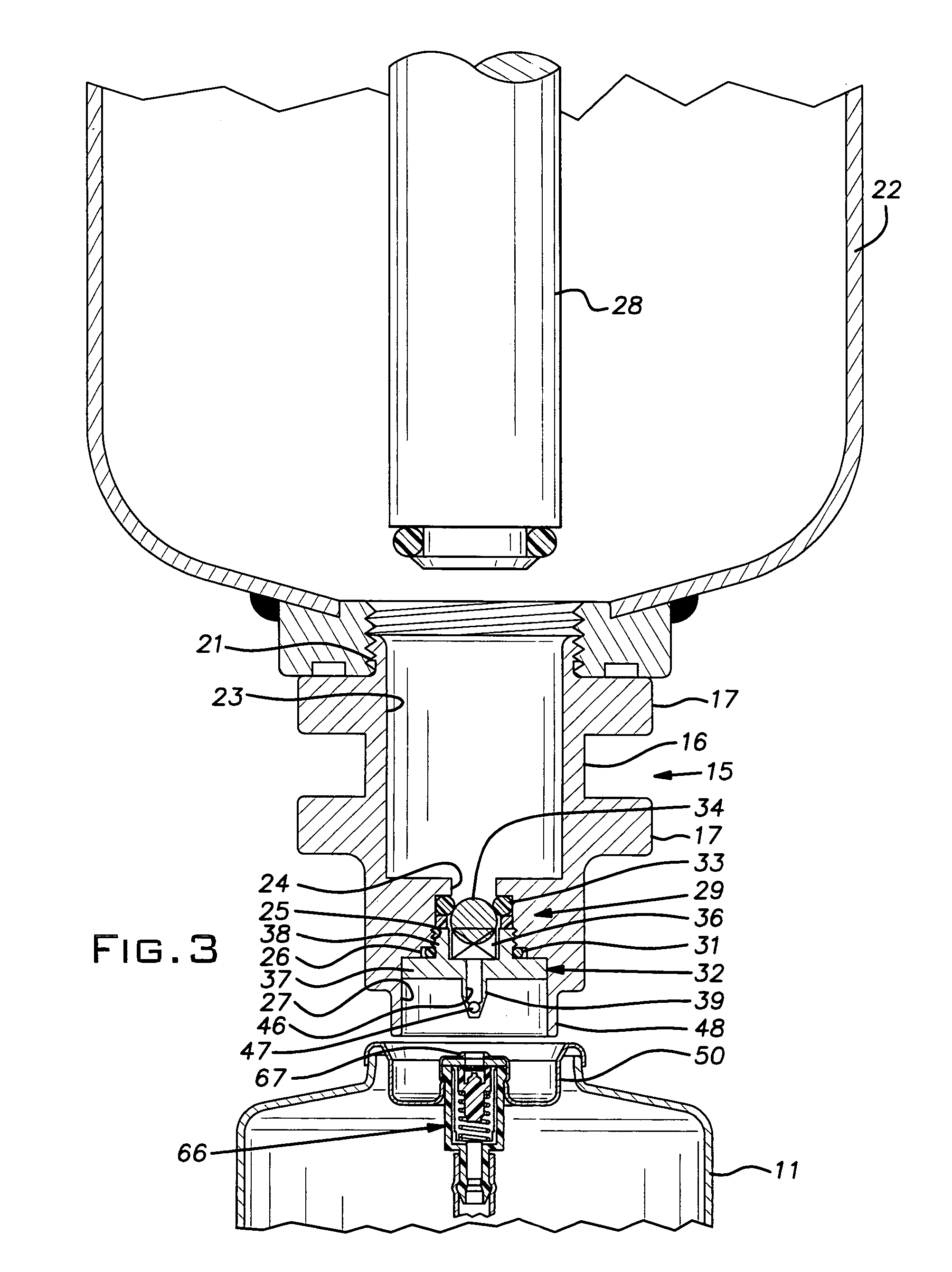
[0010]Referring now to the drawings and particularly to FIGS. 1 and 2, there is shown an aerosol can filling device 10 for injecting paint or other liquid material into an aerosol can 11 that is prefilled typically with a solution of a liquid solvent and gas propellant. The device 10 includes a rectangular housing or frame 12 preferably constructed of sheet steel. Details of the housing construction and mechanical elements within the housing are disclosed in U.S. Pat. No. 5,535,790, the disclosure of which is incorporated herein by reference.

[0011]The device 10 includes a filling head assembly 15 shown in cross-section in FIG. 3. The filling head assembly 15 includes a cylindrical body 16 having axially spaced, radially extending round flanges 17 which vertically locate the head assembly in a slot 18 in a horizontal support plate 19 carried in the frame 12. The body 16 is preferably formed of aluminum and anodized with hard coat type 3. At an upper end, the body 16 has external thre...


PUM

PropertyMeasurementUnit
Massaaaaaaaaaa
Forceaaaaaaaaaa
Diameteraaaaaaaaaa

Abstract

Filling apparatus for female valve type precharged aerosol cans includes an improved check valve construction that effectively reduces leakage and blow back while being both simple and economical. The valve comprises a seat formed of PTFE in the configuration of an O-ring. A can carrier assembly below the filling head supports the can in coupled relation with the filling head. The can carrier utilizes a relatively short compression spring to lift the can into its coupled relationship with the filling head and to laterally stabilize the lower end of the can without auxiliary guides and the like such that the carrier avoids the need for extraneous manipulation of elements other than the can itself when the can is being loaded or unloaded into the apparatus and the carrier cannot be jammed by spilled material.

Description

BACKGROUND OF THE INVENTION[0001]The invention relates to improvements in apparatus for filling aerosol cans.PRIOR ART[0002]Various devices have been created to inject paint or other material into aerosol cans precharged with solvent and propellant on a custom or other low volume basis. Examples of prior art devices are disclosed, for example, in U.S. Pat. Nos. 5,535,790; 5,647,408; 5,740,841; 5,832,965; and D361,581. Some devices have exhibited a tendency to allow propellant to leak back from a can and, in some cases, are susceptible to “blow back”. In the latter case, where significant leakage flow occurs in an injector circuit, paint or other material in a reservoir on the filling device is uncontrollably expelled by propellant in the aerosol can. This phenomena is the result of large pigment particles or dry paint particles fouling a valve seat or valve ball in the injector circuit and thereby preventing a leak proof seal being established between these valve members.[0003]Relat...

Claims


Application Information

Patent Timeline
IPC IPC(8): B65B1/04B65B31/00
CPCB65B31/003
Inventor HIRZ, DONALD J.
Owner TUNGSTEN CAPITAL PARTNERS
Why Eureka
Try Eureka