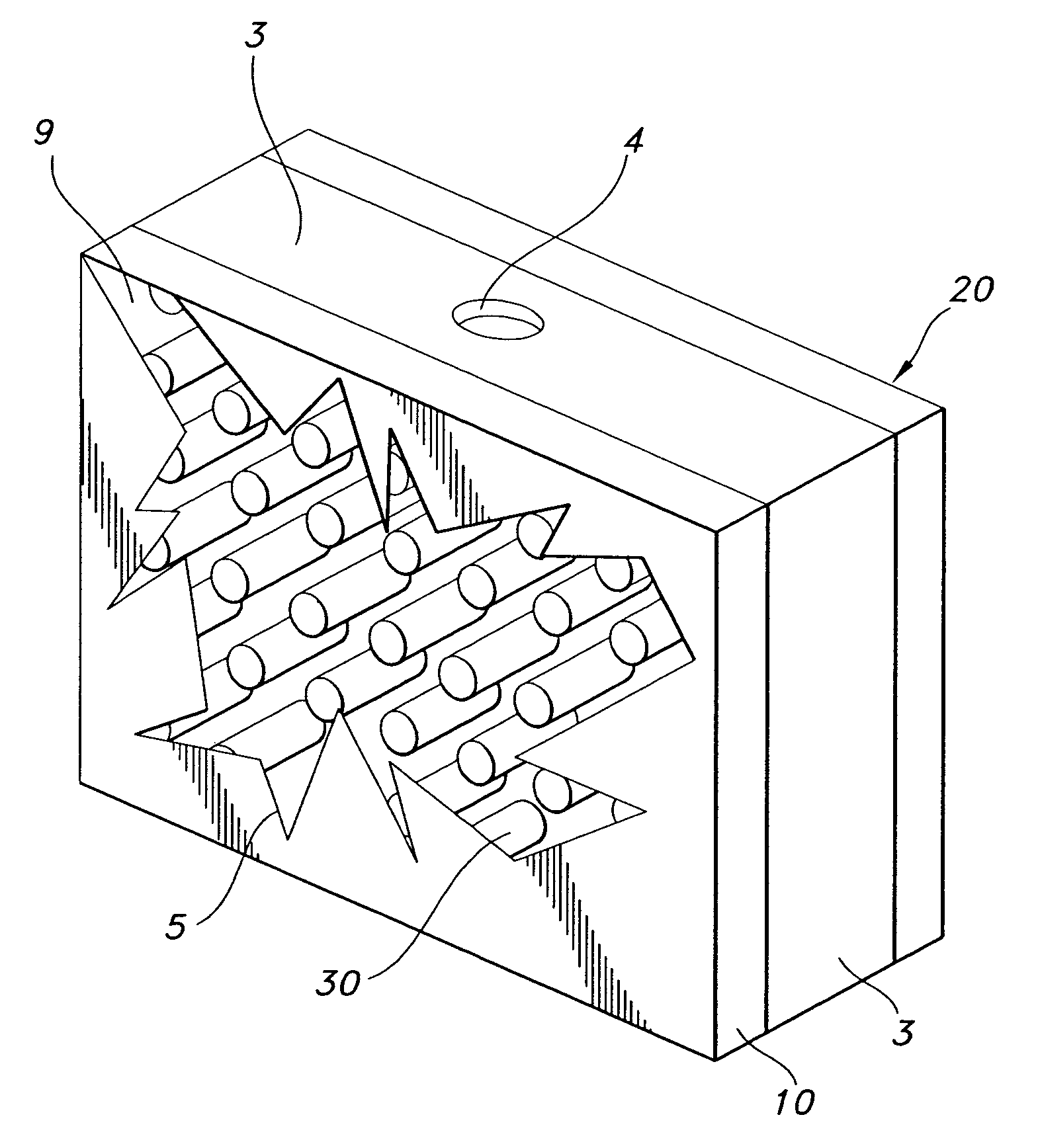
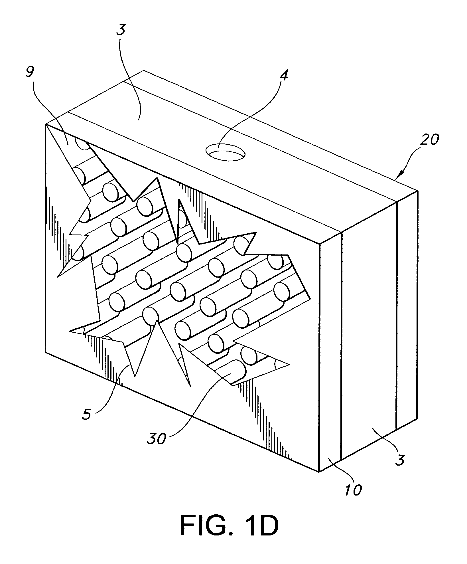
[0004]The needs are met by the present invention, where a panel is configured to inhibit the formation or propagation of a fire. According to a first aspect of the invention, a
fire protection device includes front and rear faces (or surfaces) that are spaced relative to one another by a plurality of ribs that couple the faces together. The ribs and front and rear faces define a
single chamber into which a fire extinguishing agent can be disposed. The single-chamber configuration of the present invention is distinguished over approaches that employ numerous discrete chambers (including, for example, channel- and
honeycomb-based configurations) in an effort to promote the liberation of as much fire extinguishing agent as possible from the chamber. By placing the agent into one chamber, the fracture-arresting properties inherent in the interfaces between the discrete chambers of the multi-chamber designs are avoided, thereby permitting significant agent escape from as few as one hole in the device. By having the ribs be rigidly connected to the front face, an efficient
energy transfer path between the front and rear faces is formed. Thus, upon the front face sustaining damage from an initial absorption of energy (such as, by way of example, through
ballistic impact, fire or explosion), the
coupling of the rear face, ribs and front face maximizes the transfer of the
absorbed energy to the front face to enhance front face fracture damage. The more that energy is transferred to the front face (from direct
energy impact, transferred energy from impact of the rear face that travels through the ribs, as well as energy fed back from elastic flexure of the device to which it is attached), the more likely that thorough front face fracture will occur, and consequently the more likely that at least one opening will form in the front face through which any agent present in the chamber may disperse.
[0006]In another configuration, the ribs and rear face are made from a material that imparts self-sealing features to the device. Examples of such materials include elastomers, of which rubber or related highly deformable materials are suitable, and ionomers, which are sometimes referred to as
thermoplastic elastomers. As a variation, the device can further include a layer of self-sealing material disposed adjacent the rear face. As just mentioned, this self-sealing material may be composed of an
elastomer or
ionomer. Regardless of whether or not the self-sealing feature is included, the chamber may additionally be pressurized relative to the ambient environment, such that upon a breach in one or both of the faces, the excess
internal pressure facilitates agent dispersal to the lower
ambient pressure of the adjacent area. To promote secure positioning between the fire protection device and the flammable material container, at least one mounting device can be included to secure the fire protection device adjacent the flammable material container. In a more particular configuration, the ribs are defined by size, inter-rib spacing and shape to promote the aforementioned enhanced fracture damage to the front face. Furthermore, the
coupling of the ribs to the front and rear faces is of sufficient strength to ensure the front face fractures prior to the connection between the ribs and the front face.
[0008]According to still another aspect of the invention, a fire protection device includes a front face, a rear face spaced relative to the front face, and a plurality of ribs rigidly coupling the front face to the rear face to define an
energy transfer path in a manner similar to that of the first aspect. Upon sustaining
projectile damage to the front face (such as through ballistic impact), the coupling maximizes the transfer of energy absorbed as a result of the penetration of the
projectile to the front face to enhance fracture damage thereto, thereby liberating as much of the agent as possible.
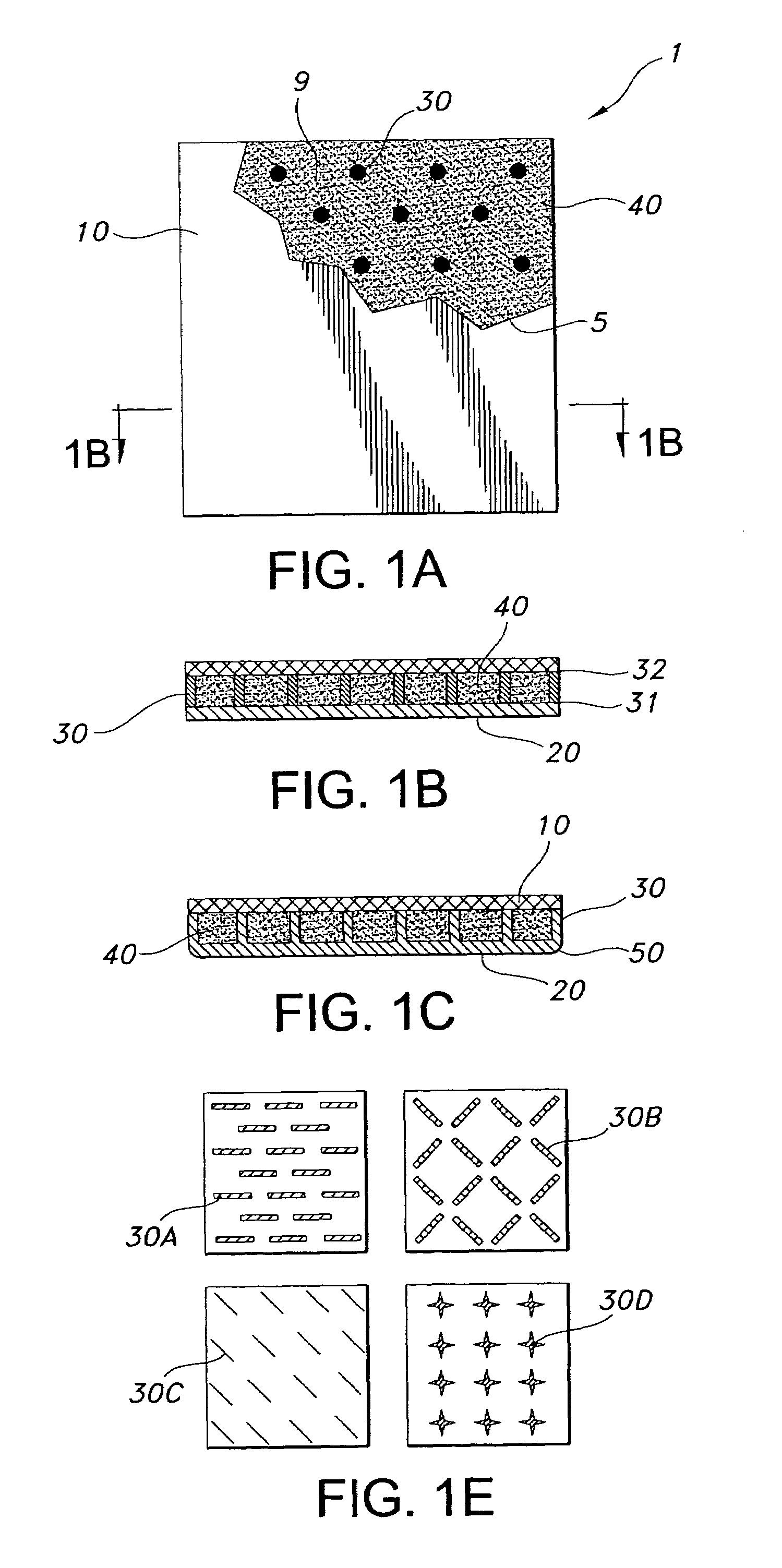
[0009]According to yet another aspect of the invention, a fire protection device for a flammable material disposed in a container includes a front face, a rear face spaced relative to the front face such that a fire extinguishing agent can be placed between them, a sealing layer disposed between the rear face and the container, and a plurality of ribs coupling the front face to the rear face. As with the previous aspects, the configuration of the device defines a
single chamber to hold fire extinguishing agent, while the coupling made possible by the rib and face connection maximizes the transfer of the
absorbed energy to the front face to enhance front face fracture damage. Optionally, the sealing layer is made of an
elastomer or
ionomer or related material responsive to a rupture forming in the container adjacent the sealing layer such that the amount of leakage of the material from the container is reduced. One example of such a compound is rubber, although it will be appreciated that others, including
intumescent materials that expand under heat
exposure, could also be employed. In an optional embodiment, the rear face, sealing layer and container are in contact with one another.
[0010]According to another aspect of the invention, a fuel
system includes a fuel container and a fire protection device coupled to the fuel container. The fire protection device is substantially similar to that discussed in conjunction with the previous aspects of the invention. The fire extinguishing agent can be in
powder, gaseous or liquid form. Similarly, the chamber can be pressurized relative to the ambient environment. In one form, the fuel container is connected to the fire protection device such that the energy due to a hydrodynamic ram (which could arise from, for example, a ballistic impact, explosion or related
overpressure in or around the fuel container) developed in the fuel container is efficiently transferred to the front face through the rear face and the ribs to effect extensive damage to at least the front face of the fire protection device. Also as previously discussed, a self-sealing feature can be included, either as a separate layer or integral with the ribs and rear face.
[0012]According to another aspect of the invention, a method of extinguishing a fire includes the steps of arranging a fire protection device that is configured similar to that of the previous aspects, and placing the fire protection device adjacent a container of the flammable material such that upon the front face of the fire protection device sustaining damage from an initial absorption of energy, the coupling between the front and rear faces and ribs maximizes the transfer of the
absorbed energy to the front face to enhance the fracture damage to the front face, thereby liberating as much of the agent contained within the device as possible. Optionally, the fire protection device can include a material that imparts self-sealing features to the device, where such material can be used for the rear face, ribs or both. As previously discussed, the material that imparts self-sealing features may be formed as a separate sealing layer disposed between the rear face and the flammable material container.

