Lifting body aircraft and reentry vehicle

Inactive Publication Date: 2005-09-27
AVIATION DYNAMICS CORP
View PDF7 Cites 13 Cited by
  • Summary
  • Abstract
  • Description
  • Claims
  • Application Information

AI Technical Summary

Benefits of technology

[0027]The inventors contemplate that the airframe will be of a single component aeroshell, with modular interior component systems. These internal component systems may include crew modules, control modules, supply modules, cargo modules, satellite modules, medical modules, evacuation modules, science or laboratory modules, propulsion modules, fuel module

Problems solved by technology

As the crafts move through air, the high profile of their curved lower surfaces causes a significant amount of air to be displaced up and around the body of the vessel.
First, pressure is being exerted on the air mass at the interface with the hull.
This will result in a decrease in pressure above the upper surface of the lifting body.
The difference between the increased pressure gener

Method used


Image

  • Lifting body aircraft and reentry vehicle
  • Lifting body aircraft and reentry vehicle
  • Lifting body aircraft and reentry vehicle

Examples


Embodiment Construction

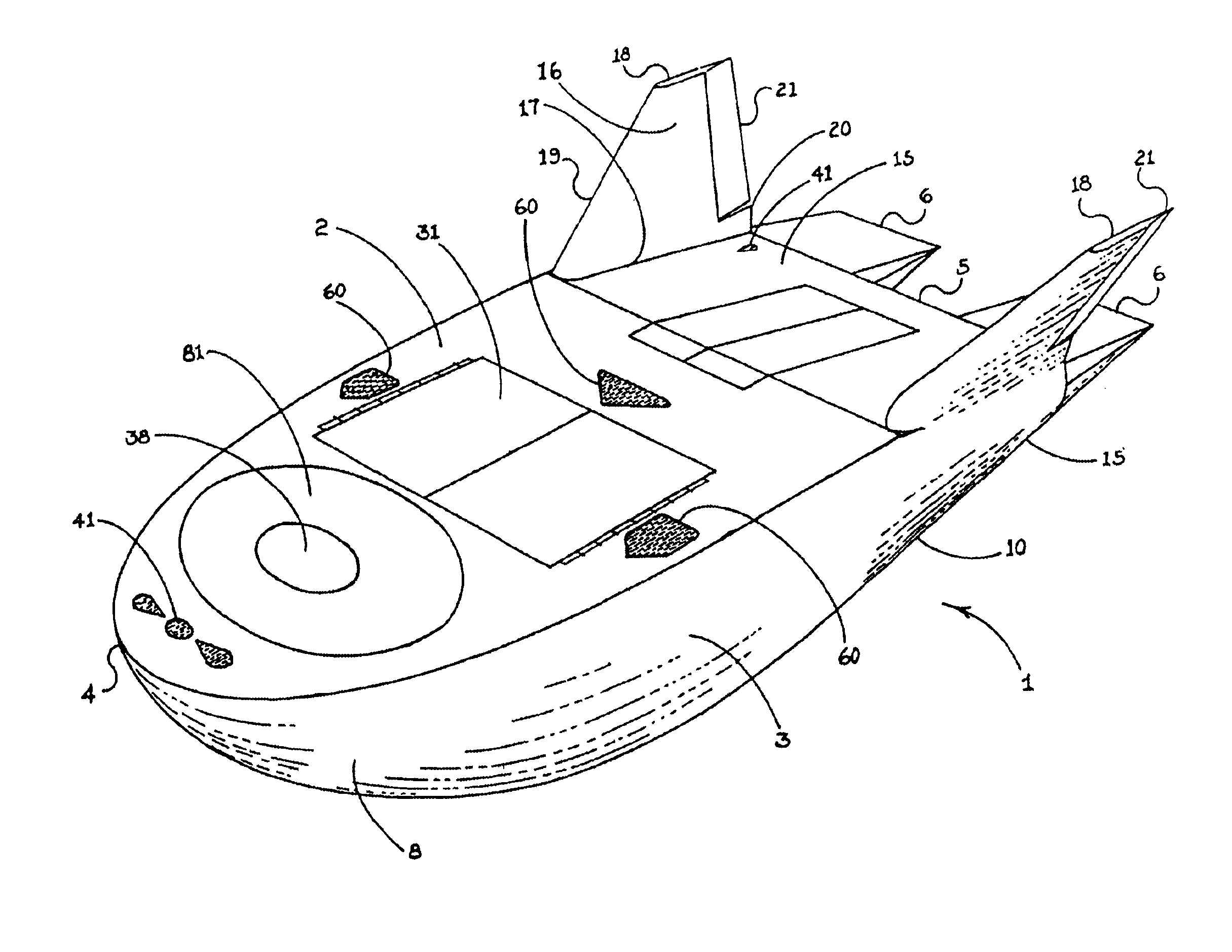
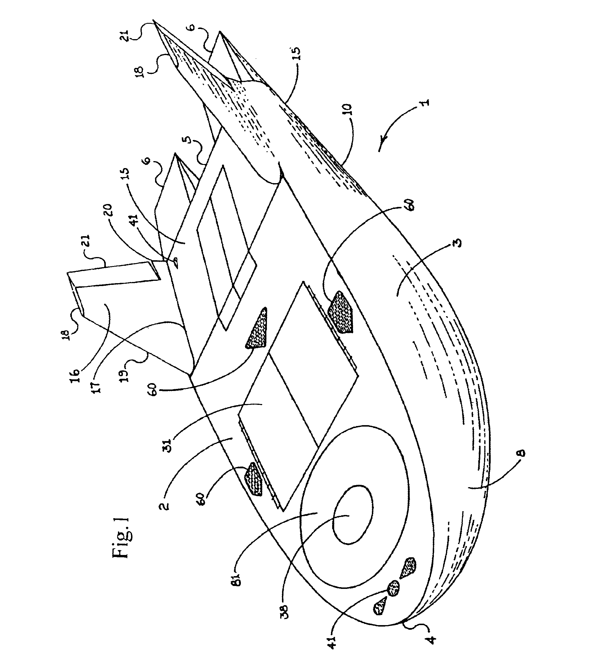
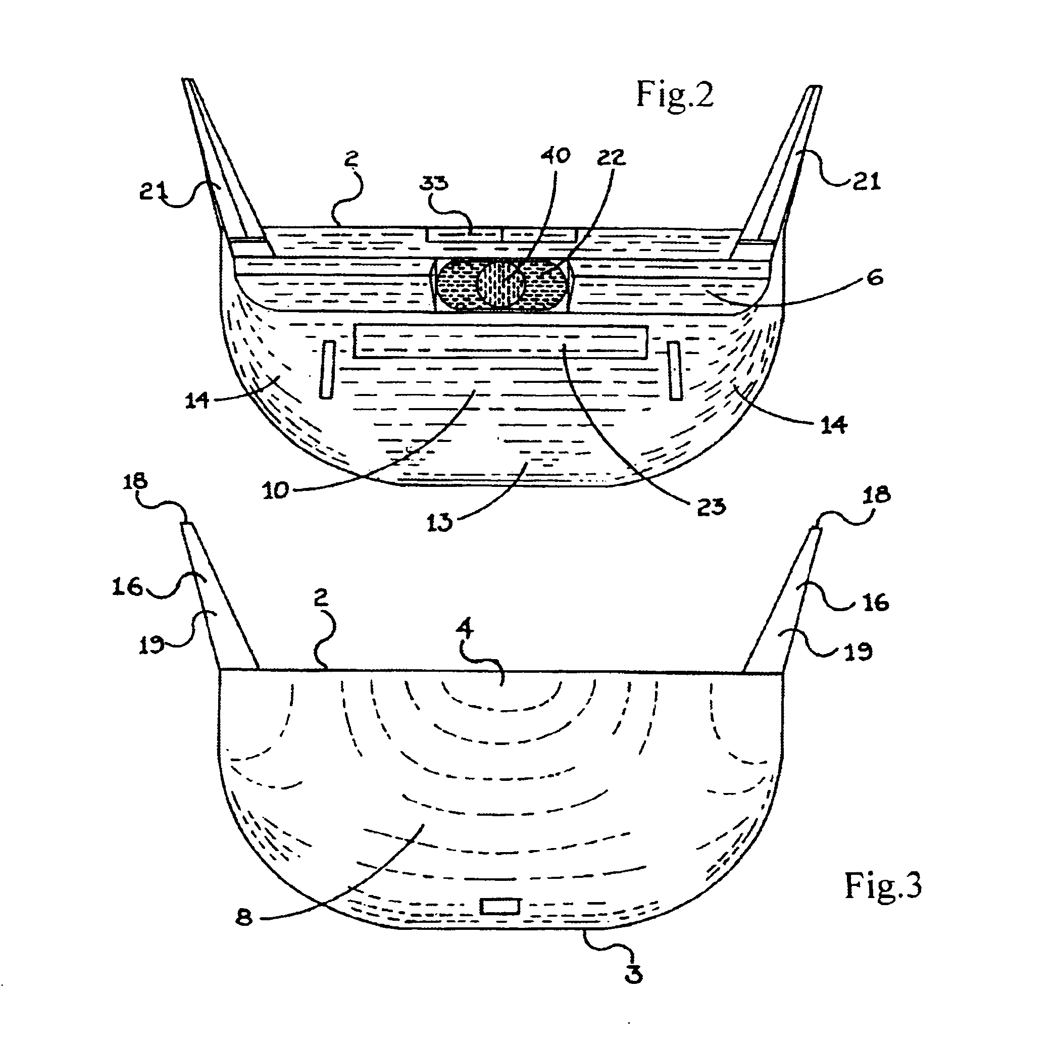
[0040]The invention comprises a lifting body aircraft 1 having an upper surface 2 and a lower surface 3. Upper surface 2 extends from the nose 4 to the tail 5 of craft 1. The length of craft 1 is that dimension extending from nose 4 to tail 5, excluding any elevons 6 (discussed below) which may be provided at the tail end or aft end 7 of craft 1.

[0041]Lower surface 3 has a first half 8 extending from nose 4 to about the longitudinal center line 9 of craft 1. The longitudinal center line 9 of craft 1 is determined by a plane severing craft 1 perpendicular to the length of craft 1 at the half way point between nose 4 and tail 5. Lower surface 3 also has a second half 10 extending from about longitudinal center line 9 to tail 5.

[0042]Upper surface 2 has a pair of edges 11 that extend from nose 4 to tail 5 such that nose 4, edges 11, and tail 5 demark upper surface 2. Edges 11 also demark two boundaries between upper surface 2 and lower surface 3. Edges 11 preferably run from nose 4 to ...


PUM


Abstract

A lifting body aircraft suitable for atmospheric flight and/or as a reentry vehicle. The craft has a substantially flat upper surface, a lower surface with a doubly convex first section and a flat sloping second section. The doubly convex first section allows the craft to have its center of gravity forward of its longitudinal center line. The flat sloping second half of the lower surface and the substantially flat upper surface form the aft end of an airfoil. A pair of vertical stabilizers enhance stability and include rudders which, along with a pair of elevons, provide steerage. The craft may glide or it may have an engine or rockets for thrust. The result is an extremely stable lifting body design that is well suited for launch or conventional take off, insertion, orbital operations, reentry, atmospheric flight, and conventional landings.

Description

BACKGROUND OF THE INVENTION[0001]1. Field of the Invention[0002]The invention relates to aircraft in general and to lifting body aircraft in particular.[0003]2. Prior Art[0004]Lifting body aircraft are known in the art. The theory was pioneered by Dr. Alfired J. Eggers, Jr. who discovered that lift could be generated by modifying the shape of a blunt nose cone reentry vehicle. Eggers'theories led to several NASA and U.S. Air Force experimental aircraft in the 1960's and 1970's, namely the M2-F1, the M2-F2, the M2-F3, HL10, X-24A and X-24B. Eggers'lift concept can also be seen in U.S. Pat. No. 3,276,722. All of these craft generate lift with the fuselage of the aircraft only; i.e. without a wing.[0005]The Eggers craft can generally be described as conical sections. They have a blunt nose, swept back sides, round bottoms, and generally flat tops. As the crafts move through air, the high profile of their curved lower surfaces causes a significant amount of air to be displaced up and ar...

Claims


Application Information

Patent Timeline
IPC IPC(8): B64C7/00B64G1/14B64G1/62
CPCB64G1/14B64G1/62
Inventor STEPHENSON, JONBAYER, JOHN C.FROESCHNER, JAMES G.
Owner AVIATION DYNAMICS CORP
Why Eureka
Try Eureka