
Liquid ejecting apparatus

a liquid ejecting and apparatus technology, applied in the direction of printing, other printing apparatus, etc., can solve the problems of limiting the reduction of impedance components, adversely affecting the quality of printing, and increasing distortion due to the impedance components of the ffc, so as to prevent the deterioration of printing quality

Inactive Publication Date: 2005-09-27
SEIKO EPSON CORP
View PDF18 Cites 7 Cited by
  • Summary
  • Abstract
  • Description
  • Claims
  • Application Information

AI Technical Summary

Benefits of technology

[0033]In a plurality of liquid ejecting apparatuses each using the FFC of a different length, an appropriate reference driving voltage of the piezoelectric vibrators is set in each type of liquid ejecting apparatus to correct a change in the reference driving voltage associated with a change in inductance components L and resistance components R of conduction patterns between the FFCs without the need to newly start up the measuring step of a driving voltage, and an appropriate driving signal waveform is thereby applied to the piezoelectric vibrators. It is thus possible to prevent irregularity in a liquid droplet ejecting speed and an ejected liquid droplet weight due to a difference in the reference driving voltage needed to drive the piezoelectric vibrators, and as a consequence, deterioration in printing quality can be prevented.

Problems solved by technology

This raises a problem that the driving voltage specified in driving voltage information ID is not applied to the piezoelectric vibrators.
This means that the position and the size of a dot formed on the surface of a sheet of paper through discharge differ with the number of nozzles from which liquid droplets are ejected for one pulse, and the printing quality is adversely influenced.
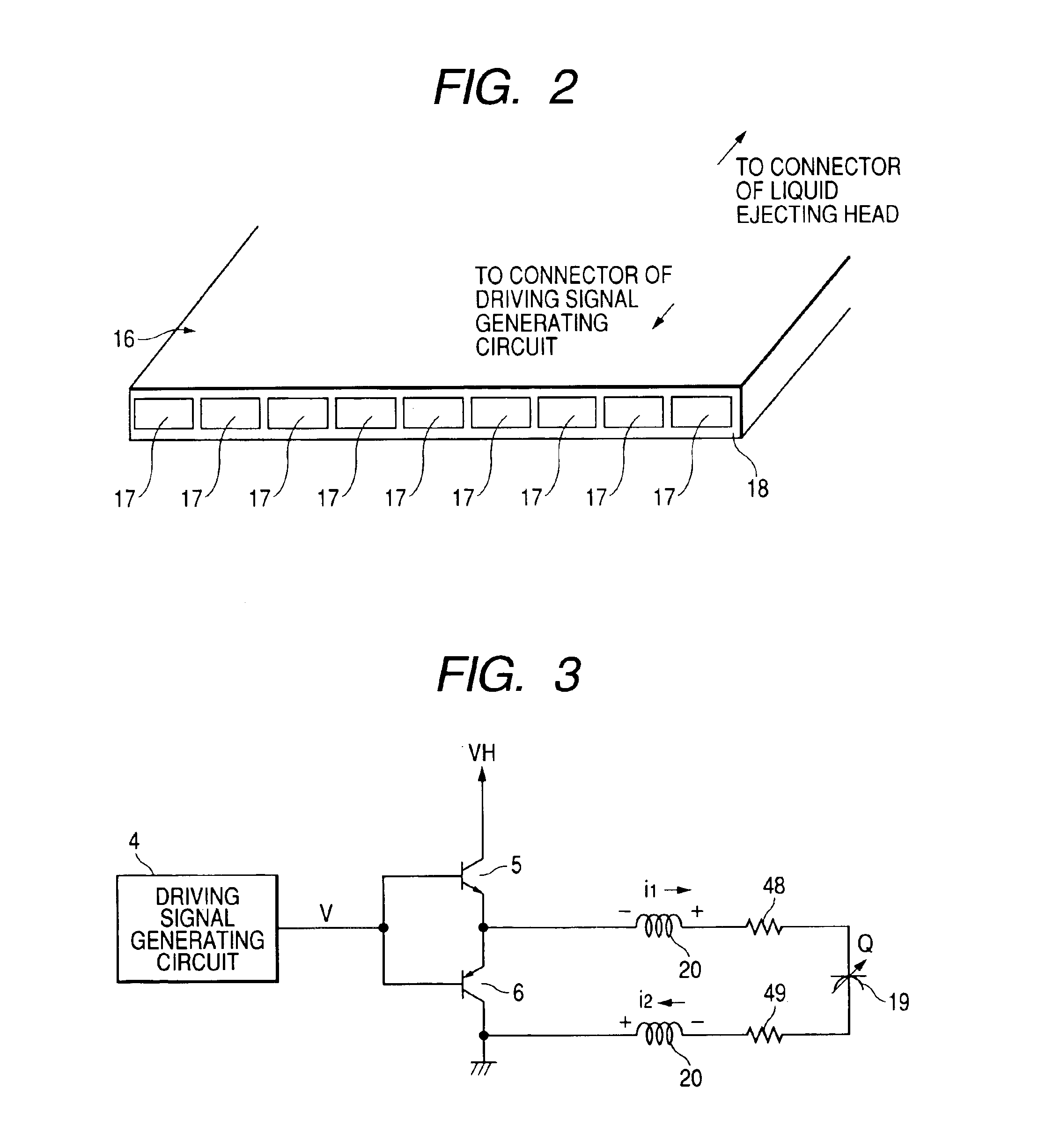
To displace the piezoelectric vibrators at a high speed, a charging and discharging time of a driving signal has to be shortened, and naturally a change rate with respect to time and an absolute value of a current are increased, which in turn increases distortion due to the impedance components of the FFC 16.
However, there is a limit to a reduction of the impedance components because of the restriction of a conducting line width and a length of the FFC 16.
It should be noted that, as a matter of course, it is impossible to shorten the FFC 16 in the LFP, and increasing the conducting line width or the number of cores of the FFC 16 results in an increase of the cost of the liquid ejecting apparatus main body 1.

Method used


Image

  • Liquid ejecting apparatus
  • Liquid ejecting apparatus
  • Liquid ejecting apparatus

Examples


Embodiment Construction

[0045]The following description will describe one embodiment of the invention in detail with reference to the accompanying drawings.

[0046]FIG. 5 and FIG. 6 are views showing one example of a schematic structure of a liquid ejecting apparatus. A flow channel unit 22 is formed by integrally laminating a nozzle plate 24 in which nozzle openings 23 are made at regular pitches, pressure generating chambers 25 that communicate with the corresponding nozzle openings 23, a flow channel formation substrate 28 provided with reservoirs 27 that supply liquid to the pressure generating chambers 25 through liquid supply openings 26, and an elastic plate 31 that abuts against the tip ends of respective piezoelectric vibrators 30 in a longitudinal vibrating mode within a corresponding piezoelectric vibrating unit 29 and thereby expands and contracts the pressure generating chambers 25 in volume. Each piezoelectric vibrating unit 29 is accommodated and fixed in an accommodation chamber 33 while bein...


PUM


Abstract

A liquid ejecting apparatus includes a liquid ejecting head formed with a nozzle opening from which a liquid droplet is ejected, and having a driving voltage information ID in a reference state specific to each liquid ejecting head, a pressure generating chamber communicating with the nozzle opening, a piezoelectric vibrator, expanding and contracting the pressure generating chamber, a driving signal generator generating a driving signal to displace the piezoelectric vibrator, a switch, selectively applying the driving signal to the piezoelectric vibrator based on liquid ejecting data, and a flexible flat cable transmitting the driving signal to the piezoelectric vibrator. A voltage obtained by adding a correction coefficient to a voltage specified in the driving voltage information ID is used as a reference driving voltage.

Description

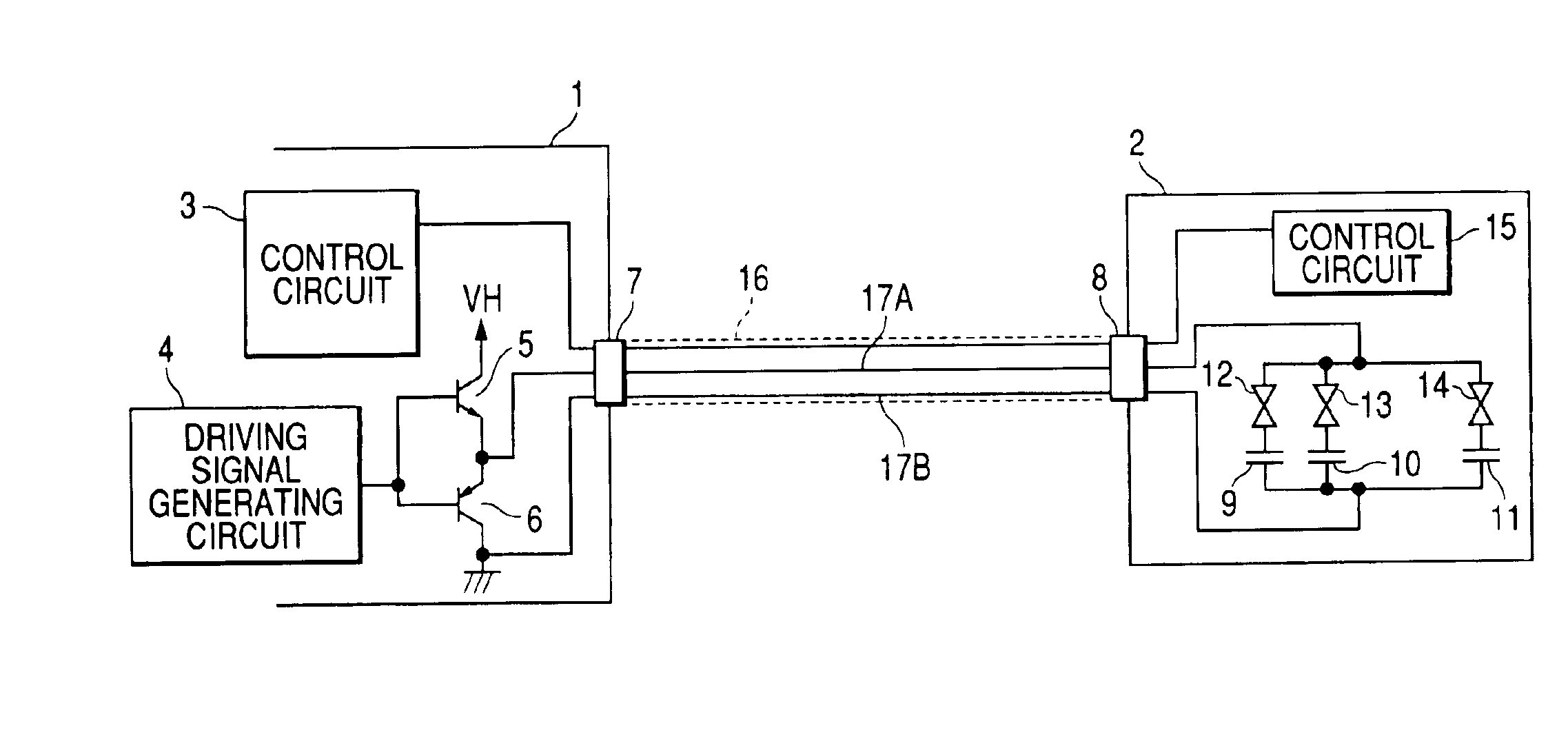
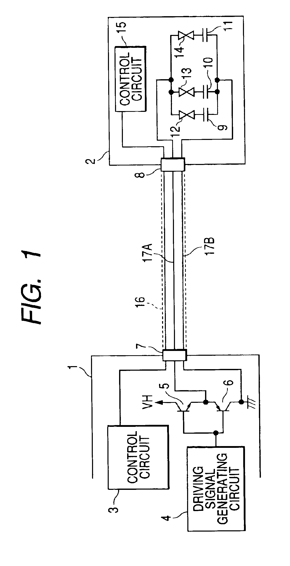
BACKGROUND OF THE INVENTION[0001]The present invention relates to a liquid ejecting apparatus equipped with a liquid ejecting head from which liquid droplets are ejected through nozzle openings by pressurizing a pressure generating chamber using pressure generator.[0002]A summary of a driving method of a related liquid ejecting head in an inkjet serial printer system as an example of a liquid ejecting apparatus will now be described with reference to the accompanying drawings.[0003]FIG. 1 is a view showing a relation between a liquid ejecting apparatus main body (hereinafter, referred to as the main body) 1 and a liquid ejecting head. The main body 1 performs information processing and supplies driving power to the liquid ejecting head 2 as a subject to be controlled. The main body 1 includes a control circuit 3 that creates data used to determine nozzle(s) which ejects liquid droplets and provides timing, a driving signal generating circuit 4 that generates a driving signal for dri...

Claims


Application Information

Patent Timeline
Patent Type & Authority Patents(United States)
IPC IPC(8): B41J2/045B41J2/055
CPCB41J2/04581B41J2/0459
Inventor TOGASHI, TAKAYUKITAKAHASHI, TOMOAKI
Owner SEIKO EPSON CORP
Learn More