Light emitting diode light bar

a technology of light bar and diode, which is applied in the direction of lighting and heating apparatus, planar/plate-like light guide, instruments, etc., can solve the problems of low cost of display, low cost of fluorescent and neon tubes, and relatively high manufacturing costs, and achieves low cost, high uniformity, and reduced cost

Inactive Publication Date: 2005-09-27
EVERBRITE
View PDF21 Cites 113 Cited by
  • Summary
  • Abstract
  • Description
  • Claims
  • Application Information

AI Technical Summary

Benefits of technology

[0005]A primary feature and advantage of the present invention is to provide a light fixture having reduced cost that provides a highly uniform, elongated light output or bar of light. The present invention uses a minimum number of light emitting diodes to achieve such an elongated output or light bar. The use of low cost light emitting diodes, translucent light guides, and novel reflective surfaces enables a uniform, elongated light output to be achieved at a relatively low cost.
[0006]The present invention comprises a lighting fixture having a translucent member or light guide that has an output surface, a curved back surface having a first reflector thereon, first and second side surfaces, an end surface, and at least one light emitting diode (“LED”) interconnected with the first end surface. In one embodiment, the first and second side surfaces are substantially planar and parallel to each other, although in another embodiment they are non-parallel and generally diverging so that the output surface is substantially wider than the back surface.
[0007]In one embodiment, the lighting fixture is modular in nature, so that lighting fixtures may be placed end to end to create an elongated light bar of any desired length. The modular unit preferably includes a first end surface having a first section and a recessed second section, with at least one light emitting diode being interconnected with the second section. The first section may be placed adjacent to a second end surface from another module so that the modules are placed end to end and thus form an elongated light bar.
[0008]A modular unit may also include several sections, each with one or more light emitting diodes and a curved back surface. Each light emitting section has a focal area toward which all light rays reflected off of the respective curve surface are directed before they proceed out of the output surface. Each light emitting section or module preferably has a blocking surface adjacent to a light emitting diode to prevent light emitted from the side of the LED from directly reaching the output surface without being reflected. This arrangement avoids non-uniform output or “hot spots”, which are areas of excessive brightness visible to the observer.
[0009]In another configuration, the invention includes two or even three adjacent LEDs on the first end surface, which are controlled by a preprogrammed controller. This enables the LEDs to be sequenced, flashed, faded or mixed to achieve a wide variety of colors and lighting effects.
[0010]In other embodiments, the light guide is formed with an air gap therein. In yet another embodiment, light diffusing particles are dispersed throughout the light guide.

Problems solved by technology

However, fluorescent and neon tubes are relatively expensive to manufacture, and require special power supplies for their operation.
Again, such displays are relatively expensive and complex.

Method used


Image

  • Light emitting diode light bar
  • Light emitting diode light bar
  • Light emitting diode light bar

Examples


Embodiment Construction

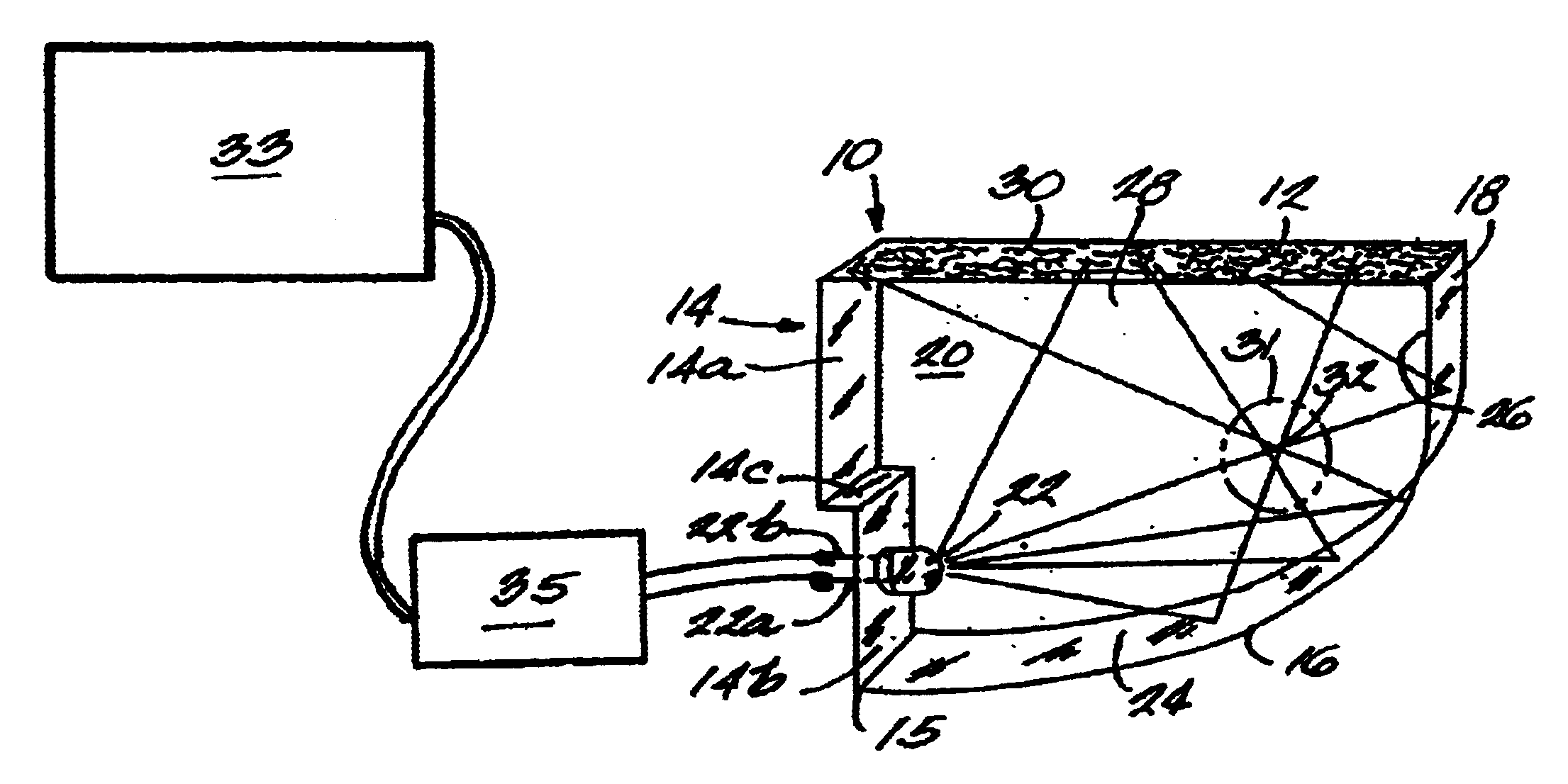
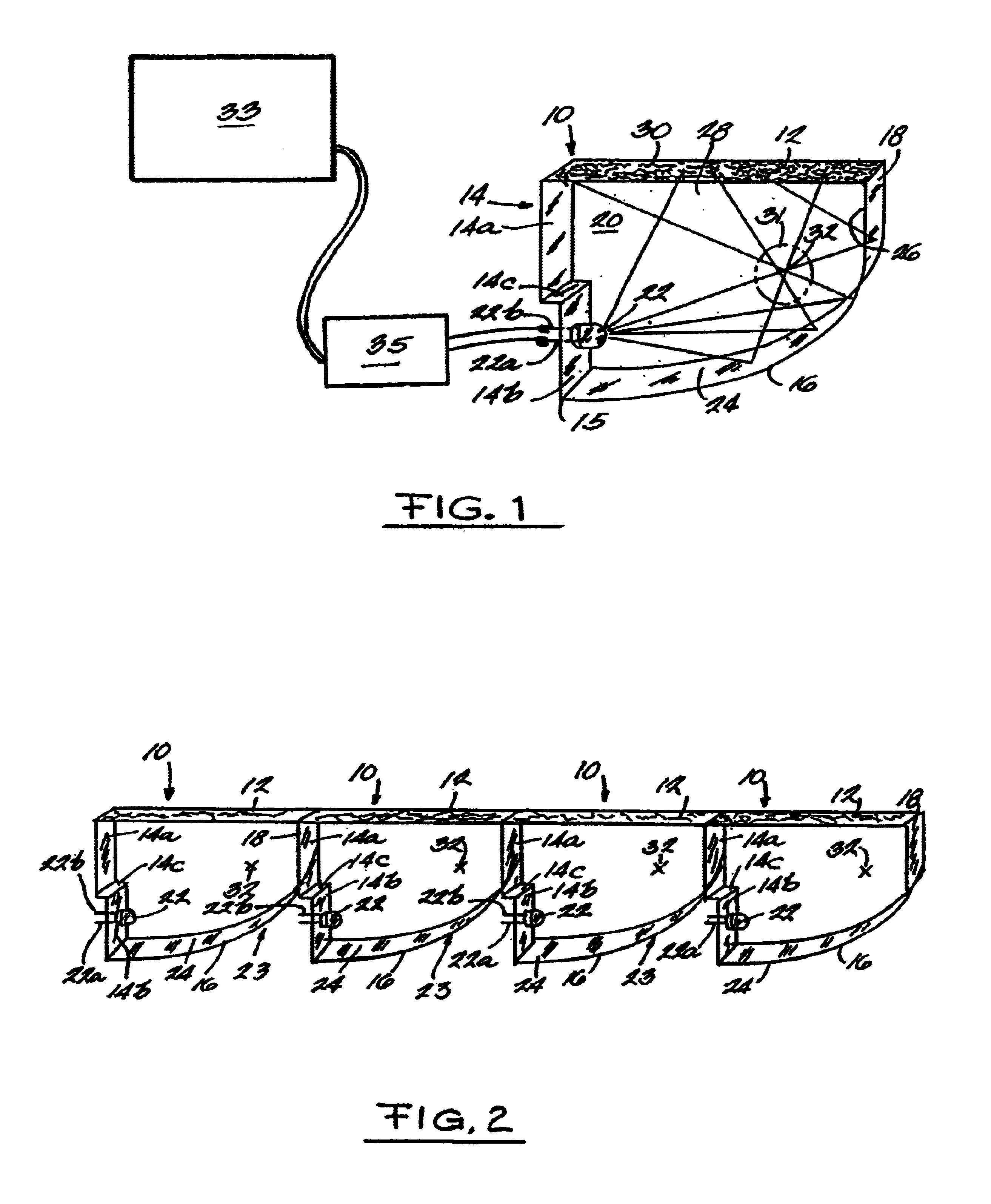
[0023]FIG. 1 depicts a first embodiment of a lighting fixture 10 according to the present invention. Fixture 10 is preferably, though not necessarily, a modular unit that may be placed adjacent to other similar lighting fixtures.

[0024]In FIG. 1, fixture 10 includes an output surface 12, a first end surface 14, a curved back surface 16, and a second end surface 18 that is opposite to first end surface 14. Output surface 12 is either clear or has a diffusive reflector or diffuser formed integral therewith.

[0025]Fixture 10 is primarily comprised of a translucent wave guide 20 made from acrylic, glass, a gel, a liquid, air, or other translucent material. It has a high total internal reflection such that there is a large difference of the index of refraction between light guide's boundaries and the surrounding medium (which is typically air). Wave guide 20 is preferably transparent at the wavelength of the output of the light emitting diode 22. Therefore, if LED 22 is a red LED, the ligh...


PUM


Abstract

A lighting fixture is disclosed which provides a substantially uniform elongated light output, yet is powered by only a minimum number of inexpensive light emitting diodes. The lighting fixture has a curved back surface and a selected focal area to provide a substantially uniform output. Multiple LEDs may be controlled by a controller to provide special lighting effects. Each of the side surfaces and the back surface may include a reflector. The lighting fixtures preferably have flat end surfaces so they may be placed end-to-end to create an elongated light bar of any desired length.

Description

[0001]This patent application claims priority from the U.S. Provisional Patent Application No. 60 / 332,702 filed Nov. 16, 2001, which is incorporated herein by reference.BACKGROUND OF THE INVENTION[0002]This invention relates to lighting fixtures. More particularly, this invention relates to lighting fixtures using light emitting diodes.[0003]It is known to use fluorescent and neon tubes to provide accent or strip lighting wherein a substantially uniform elongated light output or bar of light is desired. However, fluorescent and neon tubes are relatively expensive to manufacture, and require special power supplies for their operation.[0004]It is also known to use fluorescent and neon tubes, or liquid crystal displays as segments in a seven or fourteen segment alphanumerical character for scoreboards, signs and the like. Again, such displays are relatively expensive and complex.SUMMARY OF THE INVENTION[0005]A primary feature and advantage of the present invention is to provide a light...

Claims


Application Information

Patent Timeline
Patent Type & Authority Patents(United States)
IPC IPC(8): F21V8/00H05B33/00
CPCG02B6/0018G02B6/0021G02B6/0046G02B6/0068G02B6/0073G02B6/0078
Inventor GRENDA, CHRISTOPHERMOHACSI, FERENC
Owner EVERBRITE
Why Eureka
Try Eureka