Drill having internal chip channel and internal flush channel

a technology of internal chip and flush channel, which is applied in the field of drilling tools, can solve the problems of large cost, weakening the drill above all, and chips that are transported up through an external chip, and achieve the effect of simple manufacturing

Inactive Publication Date: 2005-09-27
SECO TOOLS AB
View PDF12 Cites 50 Cited by
  • Summary
  • Abstract
  • Description
  • Claims
  • Application Information

AI Technical Summary

Benefits of technology

[0008]Another object of the present invention is to provide a drilling tool and a blank that are simple to manufacture.

Problems solved by technology

The problem is that the chip space, for an efficient drill, must be large, which implies large costs since much material must be ground away.
The large chip spaces also weaken the drill above all in the sense of torsional and bending rigidity.
Another problem is that the chips that are transported up through an external chip space score the bore wall on the workpiece that is machined.
The known tool is made of steel, which makes no improvement regarding rigidity or stability in comparison with a conventional drill of solid cemented carbide.
In addition the known drill is complicated to manufacture and suited for drilling large holes only, i.e., generally greater than 20 mm in diameter.

Method used


Image

  • Drill having internal chip channel and internal flush channel
  • Drill having internal chip channel and internal flush channel
  • Drill having internal chip channel and internal flush channel

Examples


Embodiment Construction

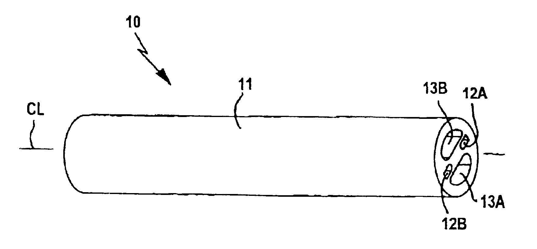
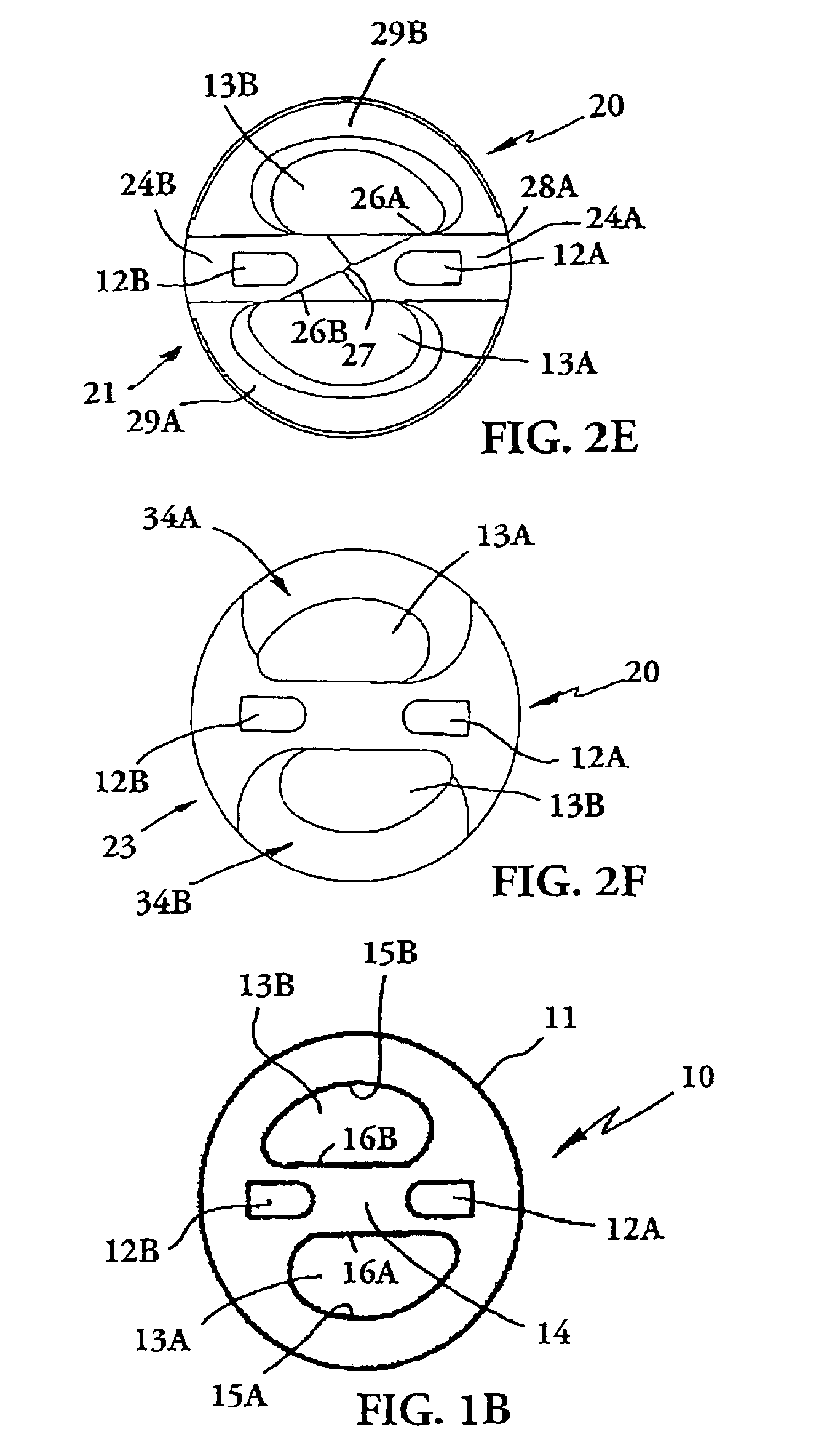
[0022]In FIGS. 1A and 1B is shown a blank 10 according to the present invention from which can be machined a drilling tool according to the present invention. The blank 10 is made of a tube 11 of cemented carbide, such as extruded cemented carbide. The blank is extruded starting from a hard constituent (for example tungsten carbide, WC) and a binder phase (for example cobalt, Co) according to the following. Cemented carbide powder with certain cobalt content and a bearer, for example plastics, is mixed and shaped into pellets or granulate. The bearer will constitute the matrix in a green body, i.e. the blank before sintering. By “cobalt” shall here be understood to mean a metallic binder phase, which alternatively can replaced by or comprise other metals, for example nickel, Ni. Subsequently, the mixture is preheated to a suitable temperature and is inserted into a machine for extrusion. Then the mixture is pressed forwards under high pressure and certain temperature, about 180° C.,...


PUM

PropertyMeasurementUnit
surface roughnessaaaaaaaaaa
diameteraaaaaaaaaa
temperatureaaaaaaaaaa

Abstract

A drill for chip removing machining includes a front cutting end, a rear securing portion, and a shank extending therebetween. The cutting end includes at least one cutting edge. The drill has at least one internal chip channel and at least one internal flush channel formed in a longitudinal pillar portion of the drill. All portions of the drill are formed of the same material, such as cemented carbide, wherein the chip channel has a surface roughness no greater than 0.5 μm.

Description

[0001]This application claims priority under 35 U.S.C. §119 to patent application Ser. No. 0301338-0 filed in Sweden on May 8, 2003, the entire content of which is hereby incorporated by reference.THE FIELD OF THE INVENTION[0002]The present invention relates to a tool, such as a drill, for chip removing machining and to a blank for making the tool.PRIOR ART[0003]A conventional cemented carbide drill has open (external) chip spaces (flutes) on its outer periphery that have been ground from a solid cylindrical bar. These bars are also available with preformed flushing holes for internal cooling. During a cutting operation, the cooling fluid flushes the chips upwardly through the chip spaces. The problem is that the chip space, for an efficient drill, must be large, which implies large costs since much material must be ground away. The large chip spaces also weaken the drill above all in the sense of torsional and bending rigidity. Another problem is that the chips that are transported...

Claims


Application Information

Patent Timeline
Patent Type & Authority Patents(United States)
IPC IPC(8): B23B51/04B23B51/06B23B51/02
CPCB23B51/0486B23B51/06B23B2222/28Y10T408/44B23B2270/30Y10T408/455B23B2228/10B23B51/02
Inventor SVENSSON, MATTIASGRONQUIST, MIKAELBRUHN, JOHNNY
Owner SECO TOOLS AB
Why Eureka
Try Eureka