Oil free screw compressor

a compressor and oil free technology, applied in the direction of positive displacement liquid engine, piston pump, liquid fuel engine, etc., can solve the problems of increasing the cost of the compressor, the compressor is insufficient, and the cost of preparing various kinds of compressors, etc., to achieve the effect of compact oil free screw compressor unit, simple and inexpensive structure, and high reliability

Inactive Publication Date: 2005-09-27
HITACHI LTD
View PDF28 Cites 5 Cited by
  • Summary
  • Abstract
  • Description
  • Claims
  • Application Information

AI Technical Summary

Benefits of technology

[0017](1) A speed increasing apparatus such as a speed increasing gear, a belt and the like is not required, so that it is possible to make the oil free screw compressor unit compact, light and inexpensive.
[0018](2) A capacity control apparatus for the suction throttling valve, the three way electromagnetic valve and the like is not required, so that it is possible to make the structure of the oil free screw compressor unit simple and inexpensive.
[0019](3) Since it is possible to employ the rotating system conventionally having a high reliability to the electric motor system and the compressor main body system by making an oscillation mechanical structure common between the electric motor system and the compressor main body system, it is possible to provide an oil free screw compressor unit capable of stably rotating to a high speed range.
[0020](4) It is possible to make the oil free screw compressor inexpensive and improve a reliability by making parts common between the electric motor system and the compressor main body system.

Problems solved by technology

Here, the compressor described in Japanese Patent Unexamined Publication No. 6-346881 mentioned above requires a lot of parts such as a bearing for rotating and supporting a speed increasing gear, a rotary shaft for mounting the speed increasing gear, a belt and a pulley for transmitting a power having an increased speed and the like in addition to a gear case for receiving the speed increasing gear, thereby causing an increase of a cost for the compressor.
Further, in this compressor, an electric motor for driving the screw rotor is enlarged, and accordingly, the compressor is insufficient in view of making small-sized a whole of the compressor unit including a stand for fixing the electric motor.
Then, in order to make the compressor as series of widely used compressors, it is necessary to combine various kinds of compressor main bodies and speed increasing gear apparatuses, thereby causing an increase of a cost in view of preparing various kinds of compressors.
As mentioned above, since it is necessary to provide with the three-way electromagnetic valve, a structure of a flow rate control system becomes complex as well as the compressor becomes expensive.
Further, in order to cancel an unloading at a time of start, a plurality of three-way electromagnetic valves are required, so that a structure of a capacity control apparatus becomes complex.

Method used


Image

  • Oil free screw compressor
  • Oil free screw compressor
  • Oil free screw compressor

Examples


Embodiment Construction

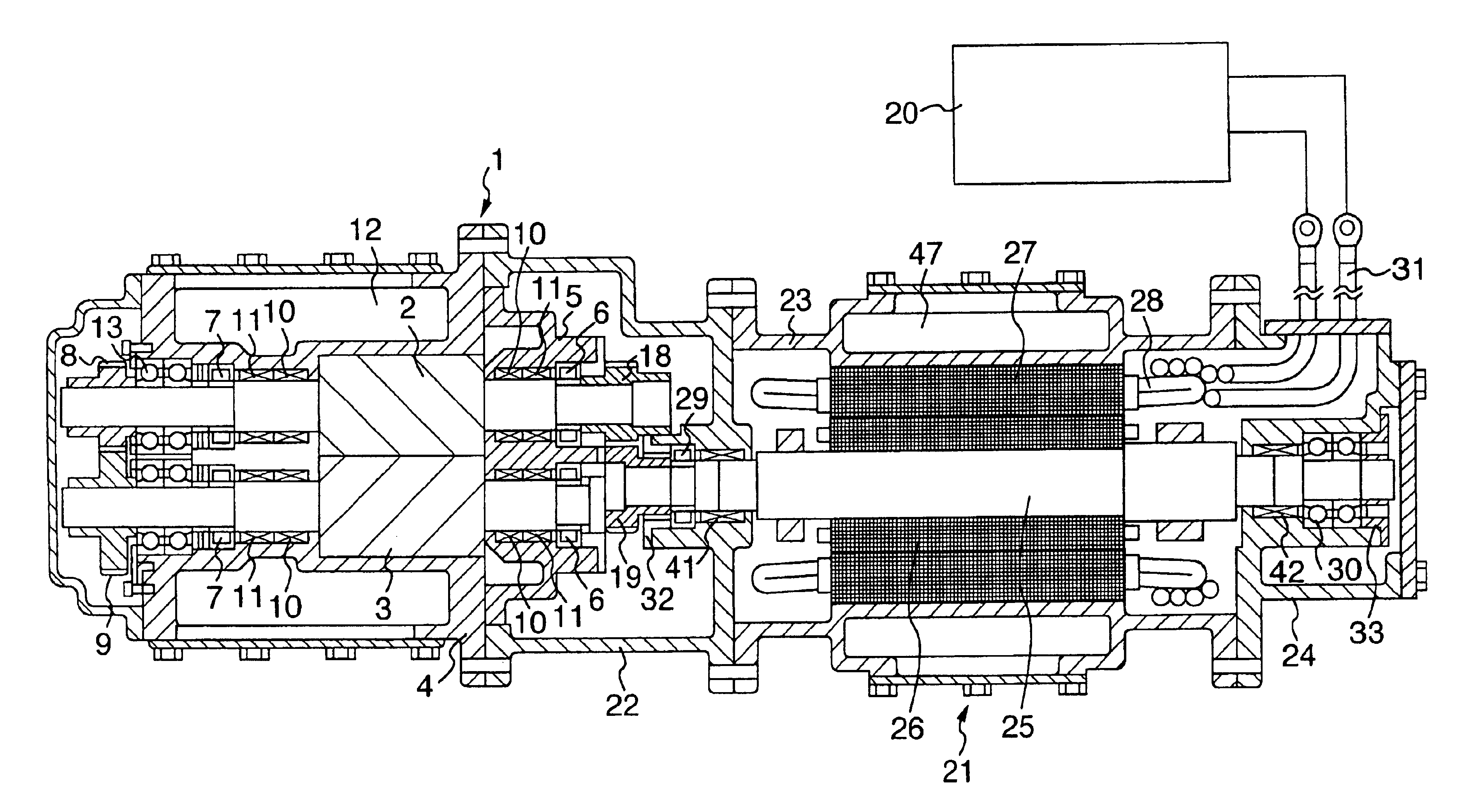
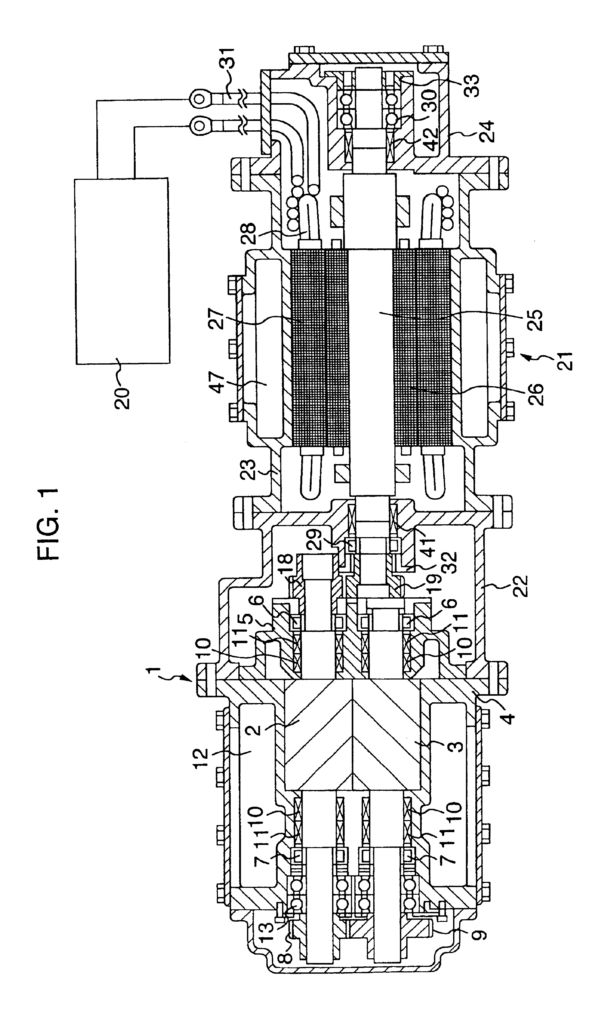
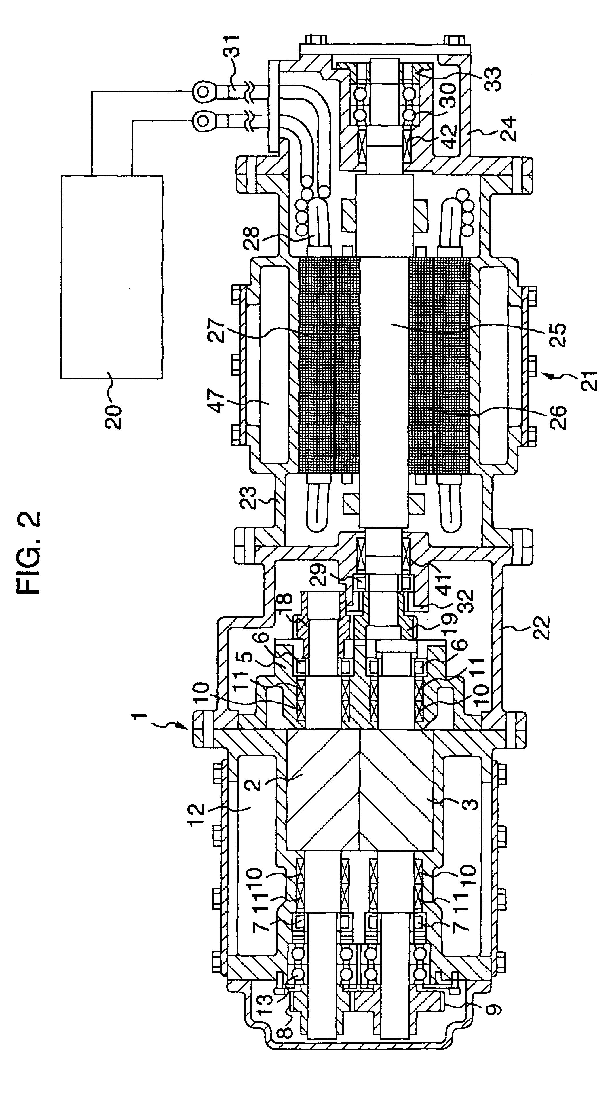
[0029]An embodiment of the present invention will be described below with reference to FIGS. 1 to 4. FIG. 1 is a view which shows a top elevational view of an oil free screw compressor driven by a high speed motor in accordance with the present invention by a cross section, FIG. 2 is a view which shows a front elevational view by a cross section, and FIGS. 3 and 4 are vertical cross sectional views which show details of a supporting portion in a motor shaft. A compressor main body 1 is structured such that tooth groove portions of a pair of male rotor 2 and female rotor meshing with each other is received in a casing 4 and drive sides thereof are received in a suction side casing 5, respectively. Then, the male rotor 2 and the female rotor 3 are rotatably supported by a suction side bearing 6 and a discharge side bearing 7 in which a lubricating oil is forcibly lubricated. In this case, a cylindrical roller bearing is employed in the suction side bearing 6, and an angular ball beari...


PUM


Abstract

A screw compressor includes a compressor main body, a male rotor having a screw-like male tooth shape and a female rotor having a screw-like female tooth shape meshing with the screw-like male tooth shape or the male rotor. The male and female motors are provided within the compressor main body. A motor casing is operably connected to the compressor main body, and a high speed electric motor provided within the motor casing. The motor includes a motor rotor, a motor stator and a motor shaft for driving at least one of the male and female rotors. A speed ratio of the motor shaft and the at least one of the male and female rotors driven by the motor shaft is in a range of 2:1 to 1:2.

Description

[0001]This application is a continuation application of U.S. application Ser. No. 10 / 224,657, filed Aug. 21, 2002, now a U.S. Pat. No. 6,638,030 which is a continuation application of U.S. application Ser. No. 09 / 828,199, filed Apr. 9, 2001 (now U.S. Pat. No. 6,471,492), which is a continuation application of U.S. application Ser. No. 09 / 391,088, filed Sep. 16, 1999 (now U.S. Pat. No. 6,287,088), the contents of which are incorporated herein by reference.BACKGROUND OF THE INVENTION[0002]The present invention relates to an oil free screw compressor which synchronously rotates a pair of screw rotors without being in contact, and more particularly to an oil free screw compressor preferable for being driven by a high speed motor.[0003]A conventional oil free screw compressor is, for example, as described in Japanese Patent Unexamined Publication No. 6-346881, structured such as to increase a rotational speed of a motor by using a belt and a gear so as to rotate a screw compressor main b...

Claims


Application Information

Patent Timeline
Patent Type & Authority Patents(United States)
IPC IPC(8): F04C18/16F04C29/04F04C29/00F04C23/00F04C2/00F04C28/06F04C28/08
CPCF04C18/16F04C23/00F04C28/06F04C29/005F04C29/04F04C2240/403F04C2/00
Inventor NISHIMURA, HITOSHI
Owner HITACHI LTD
Why Eureka
Try Eureka