Connector assembly and assembly method

a technology of connecting parts and assemblies, applied in the direction of coupling devices, two-part coupling devices, electrical equipment, etc., can solve the problems of affecting the quality of electrical equipment, affecting the reliability of electrical equipment, etc., to achieve the effect of easy installation, excellent loss and emi characteristics, and precise radius of curvatur

Inactive Publication Date: 2005-09-27
WINCHESTER ELECTRONICS
View PDF18 Cites 56 Cited by
  • Summary
  • Abstract
  • Description
  • Claims
  • Application Information

AI Technical Summary

Benefits of technology

[0026]The proximal ends of the tubular sockets are connected to the center leads of shielded coaxial cables. These coaxial cables are routed through a recess in the back of the metal housing to an interconnect in the form of a plastic carrier holding a number of pins designed to be soldered into a printed circuit board. In particular, the center lead and the shield of the coaxial cables are separately connected to individual pins of the interconnect. The coaxial cables can be easily installed and still maintain excellent loss and EMI characteristics. In particular, the coaxial cables can be routed through the recess without the need to place them in an exact position or to maintain a precise radius of curvature. High immunity to EMI can be achieved by covering the recess containing the coaxial cables with a metal backplate.
[0027]On the other hand, the foregoing metal housing can be fitted with ordinary wire leads instead of coaxial cables for applications that do not have strict requirements on avoiding losses or EMI.

Problems solved by technology

Applications employing multiple connectors can be especially vulnerable or prone to losses and EMI.
The radius of this 90 degree turn and the geometry of nearby metallic components greatly affect the losses and EMI effects, making manufacturing difficult.
Accordingly, minimizing losses and EMI considerations place significant burdens on the manufacturers of electronic equipment who may need flexibility in arranging and efficiently placing connectors on printed circuit boards.
These considerations also place significant burdens on the manufacturers of connectors who must be able to produce high-quality connectors efficiently and to develop standardized designs that can be adapted to various environments.
Stocking a large number of variously colored connectors can be inefficient for manufacturers.
Also, during manufacture or repair a wrongly colored connector may be inadvertently soldered onto a circuit board, which greatly increases the time required to complete manufacturing or repair.

Method used


Image

  • Connector assembly and assembly method
  • Connector assembly and assembly method
  • Connector assembly and assembly method

Examples


Embodiment Construction

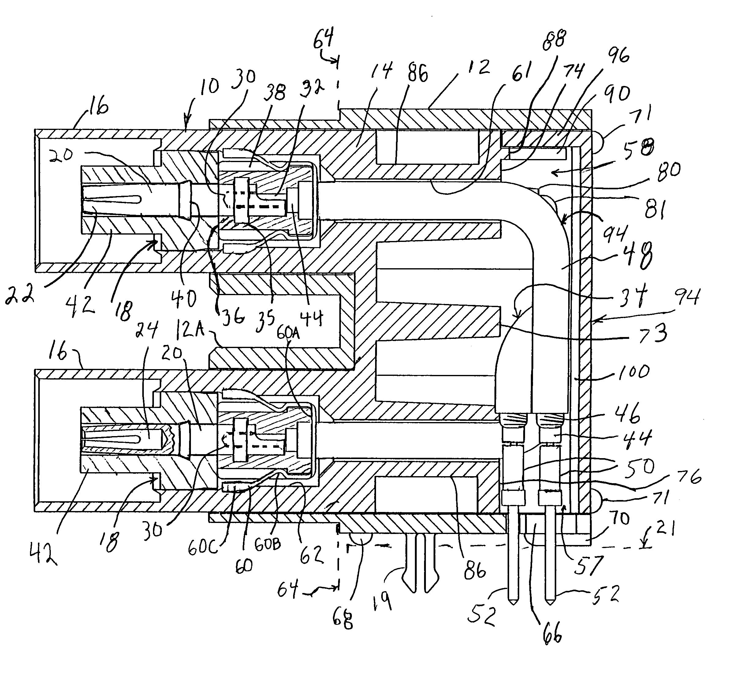
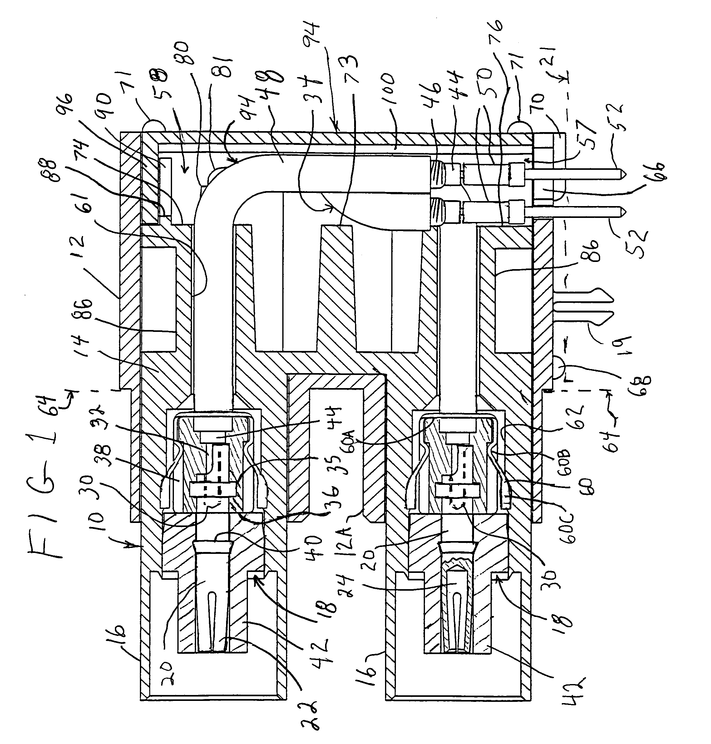
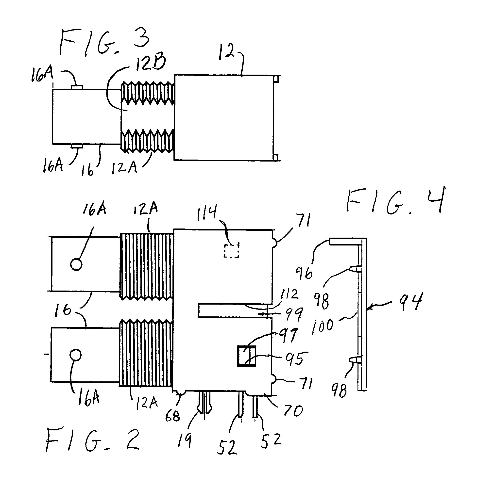
[0045]Referring to FIGS. 1–8, a connector assembly is shown as a casing having a metallic housing 10 with an insulating shell 12. The housing 10 is a zinc plated steel die casting with a rear rectangular block 14 and a pair of parallel cylindrical metal sleeves 16, encompassing openings 18, herein referred to as receptacles. Sleeves 16 are each shown with an opposing pair of stubs 16A that are typically employed in BNC connectors, although it will be appreciated that the principles of the present invention can be applied to other types of connectors. Embedded in slots 17 in housing 10 are external grounding tabs 19, shown herein as bifurcated stakes designed to snap into a hole in a printed circuit board 21 (shown in phantom).

[0046]Mounted in receptacles 18 are pair of connecting elements 20 having at their distal ends four springy, longitudinal fingers 22 distributed around a cavity 24. The proximal ends of connecting elements 20 each have a wire hole 30. The central lead 32 of shi...


PUM


Abstract

A connector assembly that is mountable on a circuit board includes a casing having a metallic housing. The housing has at least one receptacle where a connecting element is mounted. A shielded cable connects between the connecting element and an interconnect that is attached to the casing. The interconnect has a plurality of contact elements adapted to contact the circuit board. The metallic housing can be fitted with any one of variously colored insulating shells either during manufacture or in the field. The shell can later be slidably removed and replaced, even after the housing was attached to a circuit board. The casings can have dovetail slots that mate with dovetail ridges on an insert used to attach the casings together.

Description

BACKGROUND OF THE INVENTION[0001]1. Field of the Invention[0002]The present invention relates to connector assemblies and assembly methods, and in particular, to devices that are adapted for various working environments.[0003]2. Description of Related Art[0004]Simple, reliable and effective connectors are needed in various electronic applications. Also, avoiding transmission losses and avoiding the receipt or transmission of electromagnetic interference (EMI) is important in many applications involving instrumentation, test equipment and high frequency applications handling signals such as video signals, shortwave signals, walkie-talkie signals, etc.[0005]The problems with losses and EMI can be ameliorated with well-known shielding techniques, which include placing critical components inside a metal enclosure, and using shielded coaxial cables and shielded connectors that have a central lead surrounded by a cylindrical metal shell (for example, BNC or TNC connectors). In particular,...

Claims


Application Information

Patent Timeline
Patent Type & Authority Patents(United States)
IPC IPC(8): H01R9/05H01R12/16H01R13/646H01R13/658
CPCH01R13/65807H01R23/688H01R24/50H01R13/659H01R13/6592H01R13/6594H01R2103/00
Inventor BEHRENT, BOB
Owner WINCHESTER ELECTRONICS
Why Eureka
Try Eureka