Servo control system and method of setting

Inactive Publication Date: 2005-09-27
MITSUBISHI ELECTRIC CORP
View PDF16 Cites 13 Cited by
  • Summary
  • Abstract
  • Description
  • Claims
  • Application Information

AI Technical Summary

Benefits of technology

[0012]The servo control system has the adv

Problems solved by technology

In a method using the mechanical cam, it is difficult to adjust a cam pattern.
That is, it does not compensate for the follow-up delay of the servo system and thus particularly if the control speed is high, the follow-up delay of the servo system becomes noticeable as shown

Method used


Image

  • Servo control system and method of setting
  • Servo control system and method of setting
  • Servo control system and method of setting

Examples


first embodiment

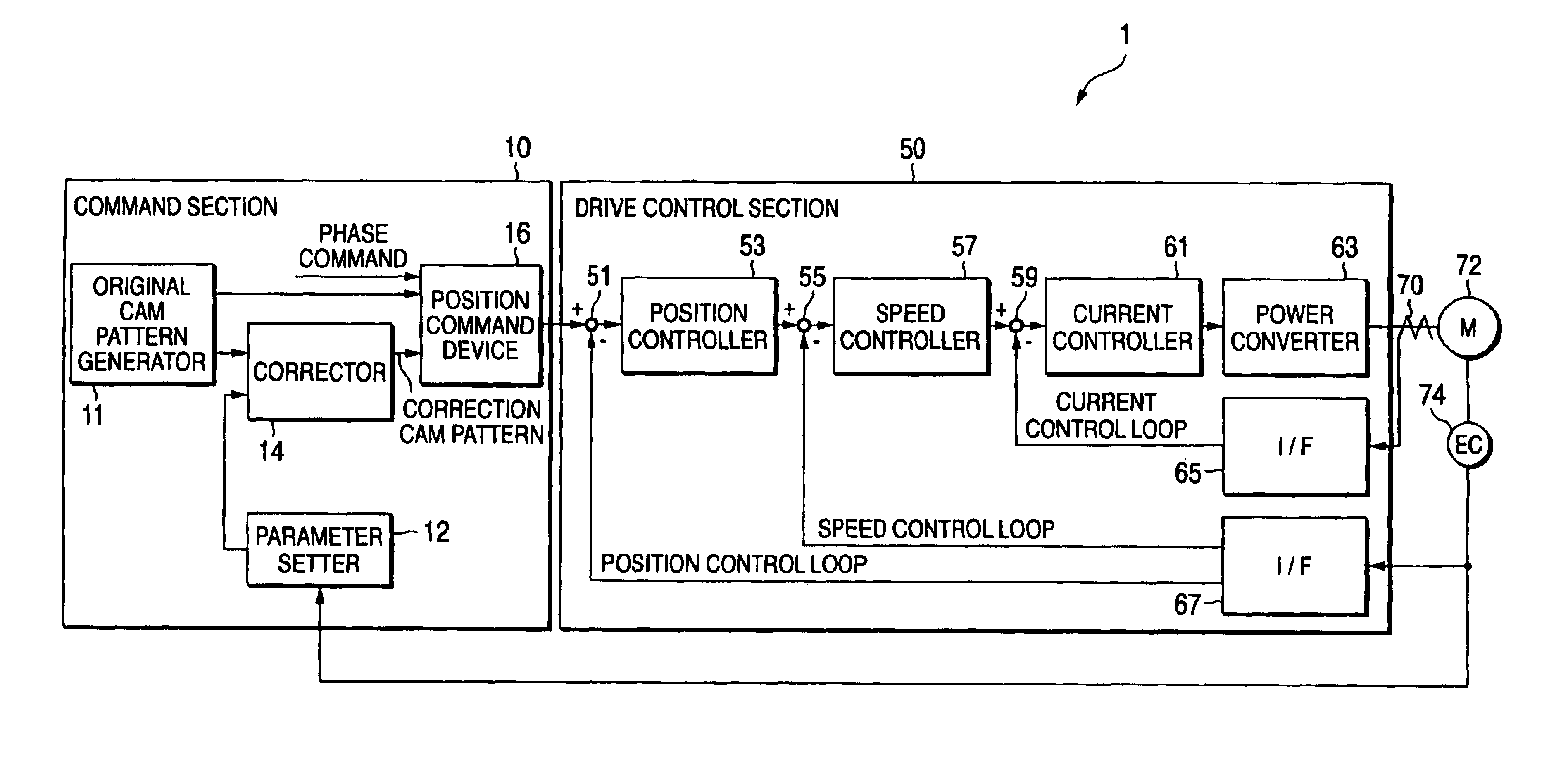
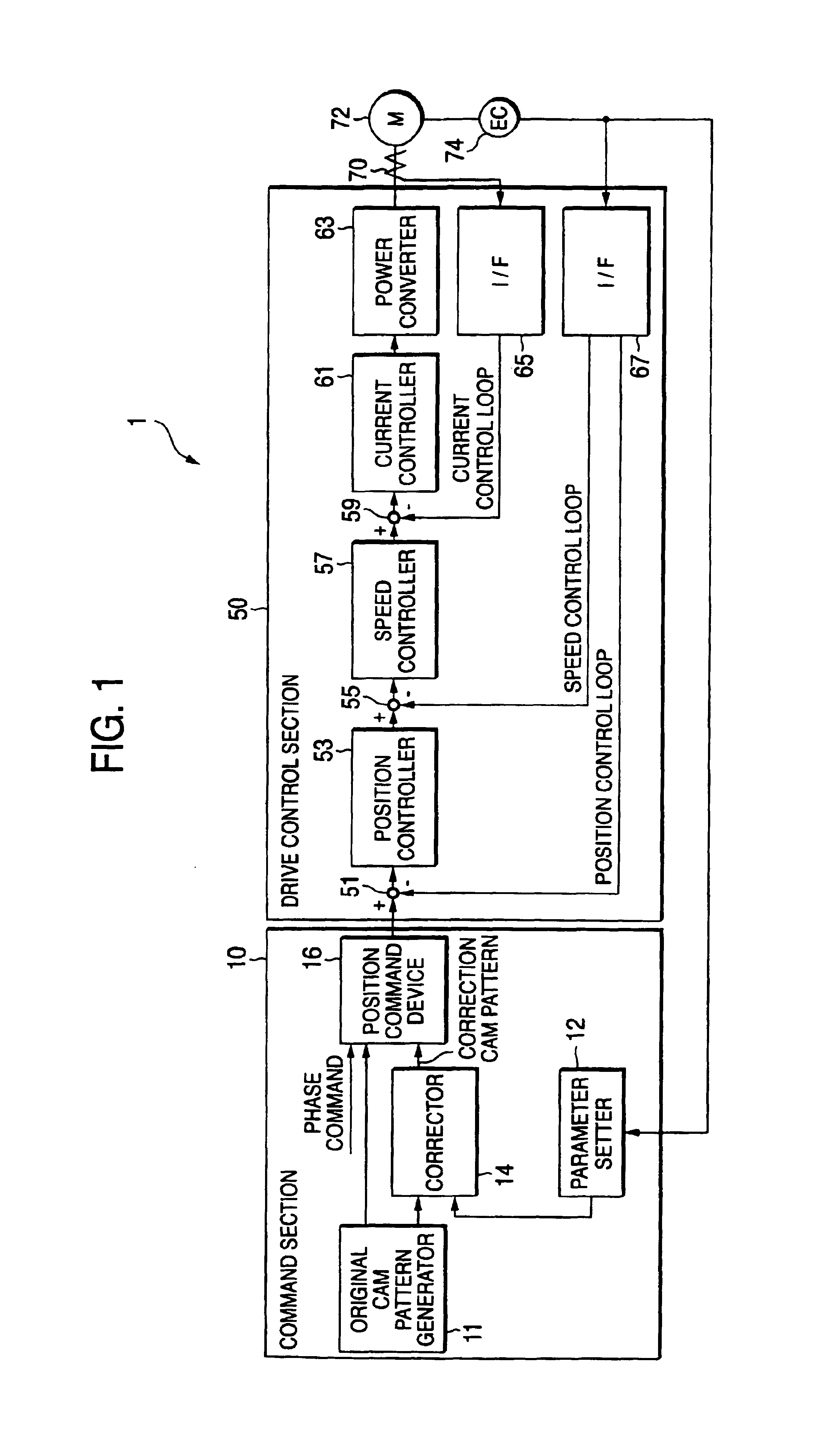
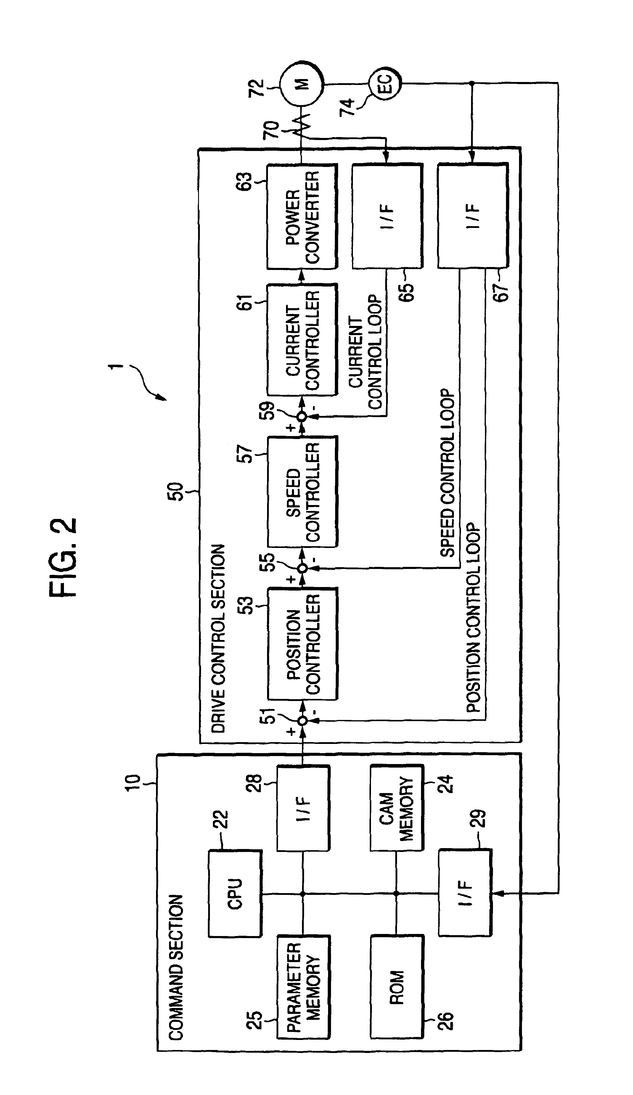
[0020]One embodiment of the invention will be discussed with reference to FIGS. 1 and 2. FIG. 1 is a general block diagram of a servo control system to show one embodiment of the invention and FIG. 2 is a general block diagram of the servo control system to show a command section shown in FIG. 1 by hardware.

[0021]In FIGS. 1 and 2, a servo control system 1 includes a command section 10 for generating a position command, a drive control section 50 for controlling drive of a servomotor 72 based on the command of the command section 10, a current sensor 70 for detecting a current flowing into the servomotor 72 and inputting to an interface (I / F) 65, and an encoder 74 for detecting the rotation angle of the servomotor 72 and inputting the rotation angle to an I / F 67.

[0022]In FIG. 1, the command section 10 indicates the processing concept of a CPU and includes an original cam pattern generator 11 as pattern generation means for generating an original cam pattern (first pattern) based on t...


PUM


Abstract

A servo control system which comprises an original cam pattern generator 11 for generating a first pattern of a cam shape relative to a phase corresponding to one revolution of a cam mechanism; a corrector 14 for differentiating the original pattern of the original pattern generator 11 with respect to time, multiplying the differentiation value by a constant to find a multiplication value, and subtracting a predetermined phase from the multiplication value to generate a correction cam pattern; and a position command device 14 for adding the above-mentioned correction pattern to the above-mentioned original pattern to generate a second pattern and generating a position command of the above-mentioned servomotor based on the phase corresponding to one revolution of the above-mentioned cam mechanism using the second pattern.

Description

TECHNICAL FIELD[0001]This invention relates to a servo control system for causing a servomotor to operate as a cam pattern according to a position command compensating for a follow-up delay in electronic cam control and a setting method of the servo control system.BACKGROUND OF THE INVENTION[0002]Hitherto, as for cam operation, a mechanical cam for providing output in conjunction with motion of a cam attached to a shaft has been used. In a method using the mechanical cam, it is difficult to adjust a cam pattern. Thus, an electronic cam has been used for which the relationship between rotation of a shaft and cam shape data is previously registered, the rotation position of the shaft is detected, and based on the detection value, a servomotor is controlled for performing cam operation.[0003]In such electronic cam control, a servo control system disclosed in JP-A-7-104855 is available for the purpose of decreasing the difference between a position command and position feedback. In an e...

Claims


Application Information

Patent Timeline
IPC IPC(8): G05B19/10G05B19/04G05B19/408G05B13/02G05D3/12G06F19/00G05B19/404
CPCG05B19/404G05B2219/43174
Inventor TOMATSURI, KAZUHIKOMATSUMOTO, HIDEHIKOIMAHASHI, AYA
Owner MITSUBISHI ELECTRIC CORP
Why Eureka
Try Eureka