Constant impedance filter

a filter and constant impedance technology, applied in the field of filters, can solve the problems of high return loss, component failure, and increase the manufacturing part count and ultimately the manufacturing cost of an ip phone, and achieve the effect of reducing the cost of ip phone replacement, and reducing the cost of replacemen

Inactive Publication Date: 2005-09-27
AVAGO TECH WIRELESS IP SINGAPORE PTE
View PDF14 Cites 8 Cited by
  • Summary
  • Abstract
  • Description
  • Claims
  • Application Information

AI Technical Summary

Problems solved by technology

The continual opening and closing of the relay creates wear and tear on the relay components as the conventional IP phone switches between the discovery and normal modes, eventually causing component failure.
Additionally, the conventional relay is not integrated with the computer or the filter, which increases the manufacturing part count and ultimately the manufacturing cost of an IP Phone.
Input frequencies that are outside of the filter passband are substantially reflected, which causes an undesired high return loss that can reduce sensitivity in the IP phone system.
Additionally, conventional filters are highly sensitive to variations in the filter components and in the variation of components that are connected to the filter.
This is undesirable as small changes in the filter components can cause large variations in the electrical characteristics of the filter.

Method used


Image

  • Constant impedance filter
  • Constant impedance filter
  • Constant impedance filter

Examples


Embodiment Construction

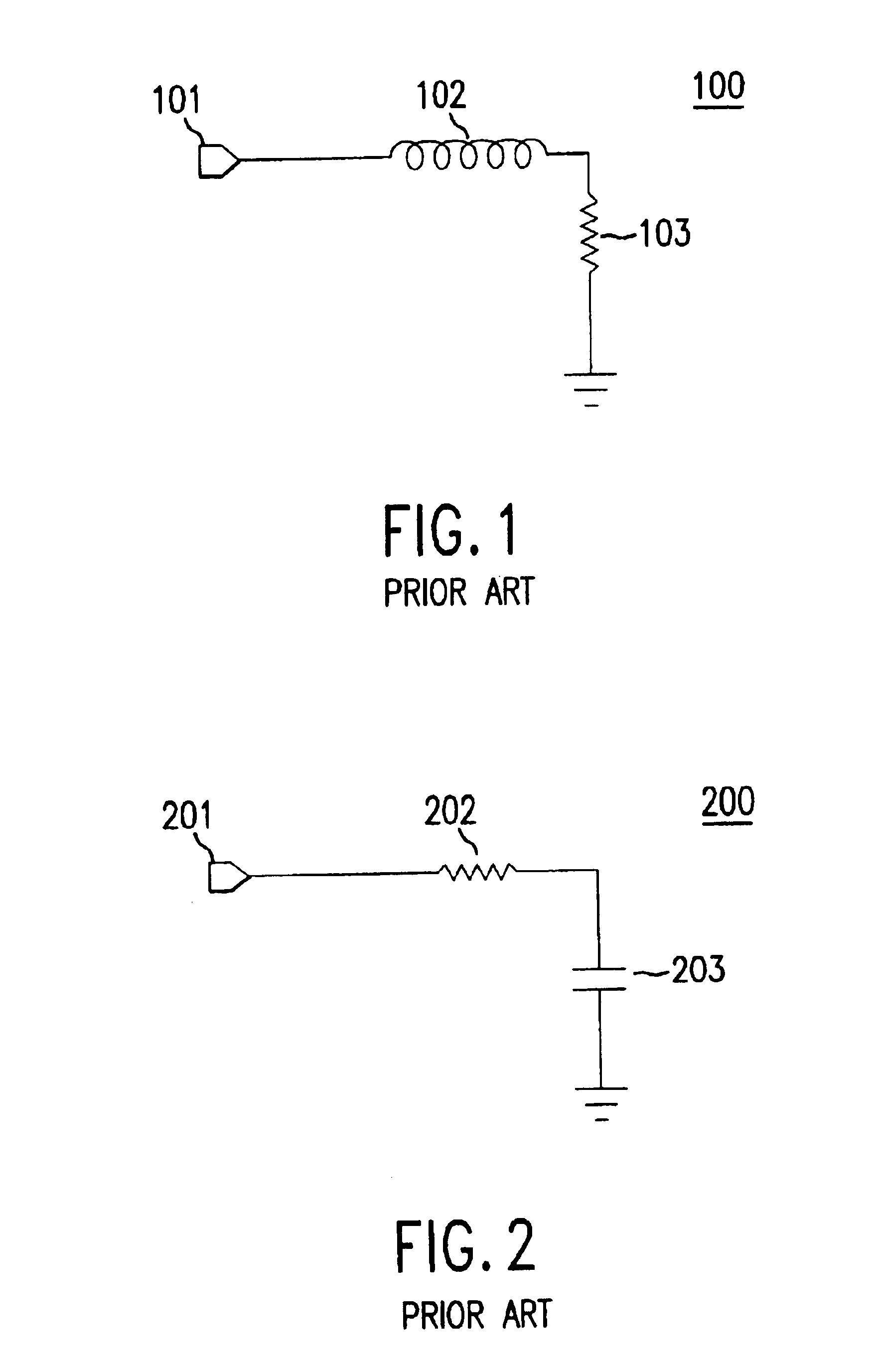
[0024]Filters are commonly used to prevent unwanted frequencies from passing to communication devices. For example, a conventionally known low pass filter consists of an inductor connected in series with a resistor. Referring to FIG. 1, a low pass filter 100 (an RL filter) is shown to have an inductor 102 connected to a resistor 103, which is grounded. One problem with the lowpass filter 100 is that the input impedance of the filter 100 is a function of frequency, as illustrated by the equations (1) and (2) below:

Z=R+sL   (1)

|Z|=√{square root over (R2+(ωL)2)}  (2)

wherein Z is the input impedance of the filter; R is resistance of the filter 102; ω is angular frequency; and ωL is inductive reactance of the inductor 102. As shown by equations (1) and (2), the input impedance of the lowpass filter 100 varies with frequency. The variable input impedance causes a variable return loss, which can decrease signal performance if there is a need for constant impedance circuitry.
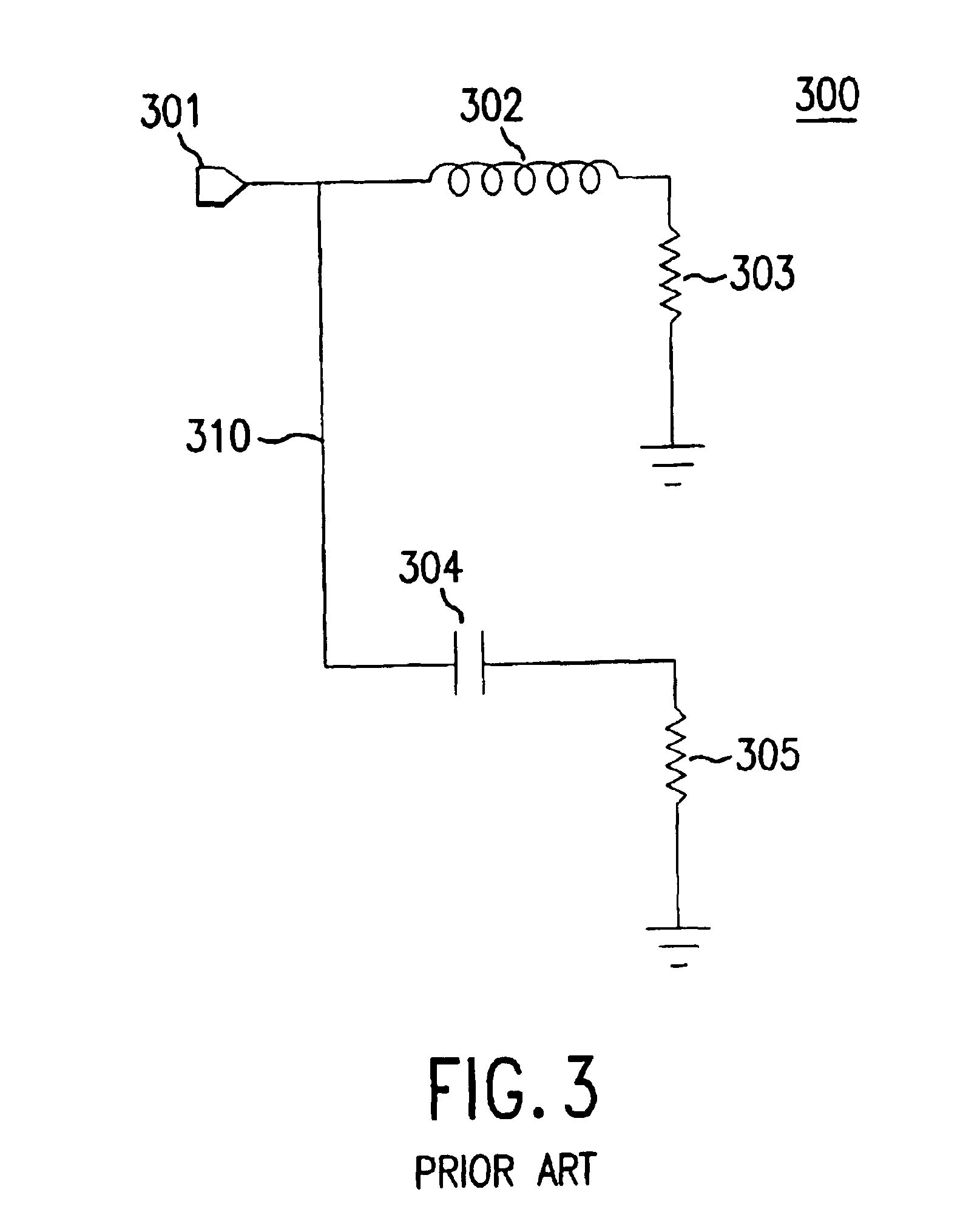
[0025]As illust...


PUM


Abstract

A constant impedance filter maintains a constant input impedance for frequencies that are both inside the filter passband and outside the filter passband. The constant input impedance appears as a pure resistance. The constant impedance filter includes a plurality of filter poles that are connected in series. Each of the filter poles include an inductor, a capacitor, and a resistor. The value of the inductor, the capacitor, and the resistor are selected to provide a constant input impedance over frequency for each pole of the filter, which produces a constant input impedance for the entire filter over frequency. The constant impedance filter can be implemented as a low pass filter, a high pass filter, or a bandpass filter. Furthermore, the constant impedance filter can be implemented in a single-ended configuration or a differential configuration.

Description

CROSS-REFERENCE TO RELATED APPLICATIONS[0001]This application is a continuation of U.S. patent application Ser. No.09 / 986,752, filed on Nov. 9, 2001now U.S. Pat. No. 6,608,536, which claims the benefit of U.S. Provisional Application No. 60 / 246,991, filed on Nov. 9, 2000, both of which are incorporated by reference herein in their entirety.BACKGROUND OF THE INVENTION[0002]1. Field of the Invention[0003]The present invention is related to a filter having a constant input impedance over frequency.[0004]2. Background Art[0005]In addition to data communications, the Internet can also be used to carry voice telephony. One conventional system that carries voice communications over the Internet utilizes an Internet Protocol (IP), and such telephones are referred to as IP telephones.[0006]The data terminal equipment (DTE) of an EP telephone includes a telephone line that is connected to a computer device through a series-connected relay (i.e. switch). The relay switches an incoming telephon...

Claims


Application Information

Patent Timeline
Patent Type & Authority Patents(United States)
IPC IPC(8): H03H7/01H03H7/06H03H7/075
CPCH03H7/06H03H7/075H03H7/1758H03H7/38H03H7/425
Inventor FALLAHI, SIAVASH
Owner AVAGO TECH WIRELESS IP SINGAPORE PTE
Why Eureka
Try Eureka