Multiple-triggering alarm system by transmitters and portable receiver-buzzer

a multi-triggering, alarm system technology, applied in the direction of electric/electromagnetic visible signalling, visible signalling systems, transmission, etc., can solve the problems of limiting movement, requiring sustained or even constant attention,

Inactive Publication Date: 2005-09-27
BELLONE RAYMOND +1
View PDF14 Cites 118 Cited by
  • Summary
  • Abstract
  • Description
  • Claims
  • Application Information

AI Technical Summary

Benefits of technology

[0002]The central transmitter box contains a battery (with an electroluminescent bicolor—LED—which indicates the state of charge of the battery). In the event of a power cut of the mains supply, this battery provides power for the system operate for several hours: a charger to charge up the battery in the central transmitter and to charge up the portable vibrating-receiver. The central transmitter box also contains a transmitter, which can send out a coded radio wave (programmable by an encoder with a switch). This signal activates or deactivates the presence detector(s).
[0003]The central transmitter has a range and maximum frequency that comply with the law. This transmitter triggers the vibrator-motor in the portable vibrating-receiver box as well as the red LED that is located on the outside of the portable vibrating-receiver box. Four different possible ways of using the central transmitter box exist: The first way is to manually push on the “alarm” pushbutton, which triggers the signal sent out by the central transmitter to the portable vibrating-receiver that activates the vibrator-motor it contains, the red LED located on the portable vibrating-receiver box as well as a LED indicator on the central transmitter box indicating that the order sent out by the pushbutton “alarm” has been correctly transmitted and registered by the receiver; this indicator remains active until somebody presses on the “clearance” pushbutton located on the central transmitter box. The second way is by using a clock that can be programmed to trigger the signal from the central transmitter to the portable vibrating-receiver. This signal activates the vibrator-motor and the red LED located on the outside of the portable vibrating-receiver box. It is possible to program several cycles per day at different times and to program over an eight-day period. This clock synchronizes itself automatically whenever it encounters a transmission ray of DCF 77 radio signals. The third way is by using a voice / sound detector (voices, crying, noises) with a microphone and potentiometer for adjusting the frequency sensitivity. This sound detector triggers the signal in the central transmitter to the receiver in the portable vibrating-receiver box, which activates the vibrator-motor as well as the red LED located on the outside of the portable vibrating-receiver box. The fourth way is by using a pushbutton (lit up=active) to activate or deactivate the (unwanted intruder) presence detector(s). On the outside of the central transmitter box there is a manual reversing switch (cursor), which can be used to switch the order from the clock or the order from the voice / sound detector, or to connect or disconnect both of these. On the central transmitter box there is a housing with two golden and fool proofed contacts to receive the portable receiver-vibrator and charge up its battery, an antenna, a mains output with cord and protection, a green LED diode for the mains power supply, a potentiometer to adjust the voice / sound detector, a bicolor LED diode to indicate the state of charge of the portable vibrating receiver battery (red =discharged / green=charged). In the presence detector transmitter box there is a battery so that, in the event of a power cut of the mains supply, the system can continue to function for several hours. In the presence detector transmitter box there is a presence detector system, a receiver receiving a coded radio wave signal from the central transmitter that activates or deactivates the presence detection system as well as a transmitter which, once it is activated by the impulse from the presence detector, sends out a coded wave signal (programmable by a switch encoder—with a range and maximum frequency that comply with the law) to the receiver that triggers the vibrator-motor in the portable vibrating-receiver box as well as the three LEDs (red, yellow and green) located on the outside of the portable vibrating-receiver box. On the outside of the presence detector transmission box is the exterior part of the presence detection system, an antenna, a mains output, a light which is activated by the presence detector whenever a presence is detected, a red LED, which indicates that the presence detection system is activated as well as a green LED for the mains power supply. In the telephone plug transmitter box there is a battery so that, in the event of a power cut of the mains supply, to system can continue to function for several hours. In the telephone plug transmitter box there is also a transmitter which, once it is activated by the impulse from the telephone ring, sents out a coded wave signal (programmable by a switch encoder—with a range and maximum frequency that comply with the law) to the receiver that triggers the vibrator-motor in the portable vibrating-receiver box as well as a green LED located on the outside of the portable vibrating-receiver box. On the outside of the telephone plug transmitter box there is an antenna, a mains output, a male / female telephone plug as well as a green LED for the mains power supply. In the front door transmitter box there is a battery so that, in the event of a power cut of the mains supply, the system can continue to function for several hours. In the front door transmitter box there is also a transmitter which is activated by pressing on the pushbutton located on the outside of the box. As soon as it is activated this transmitter sends out a coded wave signal (programmable by a switch encoder—with a range and maximum frequency that comply with the law) to the receiver that triggers the vibrator-motor in the portable vibrating-receiver box as well as a yellow LED located on the outside of the portable vibrating-receiver box. On the outside of the front door transmitter box there is a push-button, an antenna, a mains output as well as a green LED for the mains power supply. The device, as defined by this invention, also consists of a portable vibrating-receiver box inside which there is a receiver (with its decoder and its switch coded with the switches from the different transmitters) that can receive a coded signal of a frequency and maximum range that comply with the law from anyone of the transmitters, a vibrator-motor, a battery to power the system, an antenna. On the outside of the portable vibrating-receiver box there are two golden contacts with which the receiver battery can be charged up, a watch, three LEDs that indicate from where the coded wave is sent (all three=presence detector transmitter, red=central transmitter, green=telephone plug transmitter, yellow=front door transmitter).

Problems solved by technology

At the present time, the existing devices are sound warning systems—which can be awkward in some situations or places—or visual (light flashes), which considerably limit movement and also require sustained, or even constant attention.

Method used


Image

  • Multiple-triggering alarm system by transmitters and portable receiver-buzzer
  • Multiple-triggering alarm system by transmitters and portable receiver-buzzer
  • Multiple-triggering alarm system by transmitters and portable receiver-buzzer

Examples


Embodiment Construction

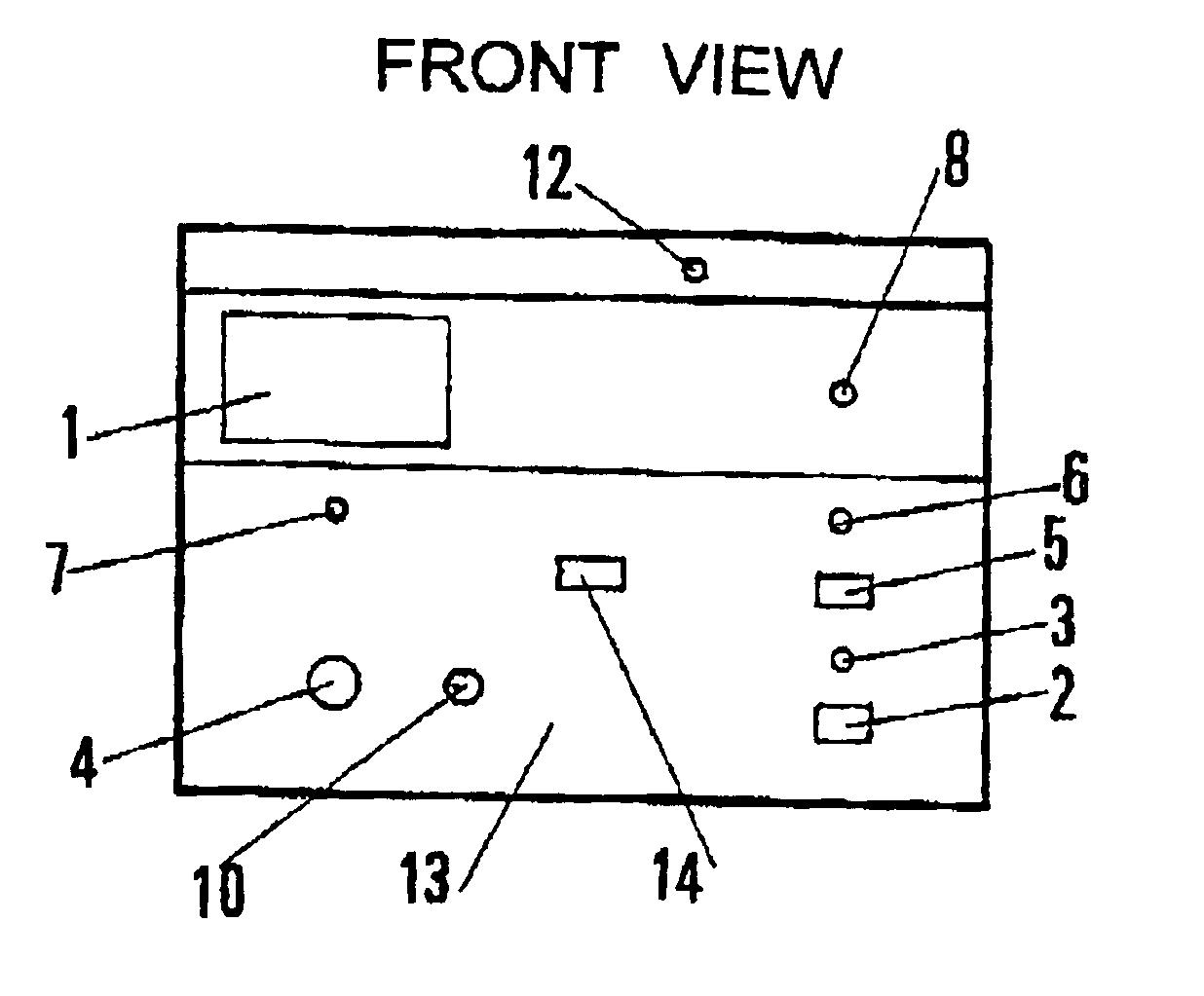
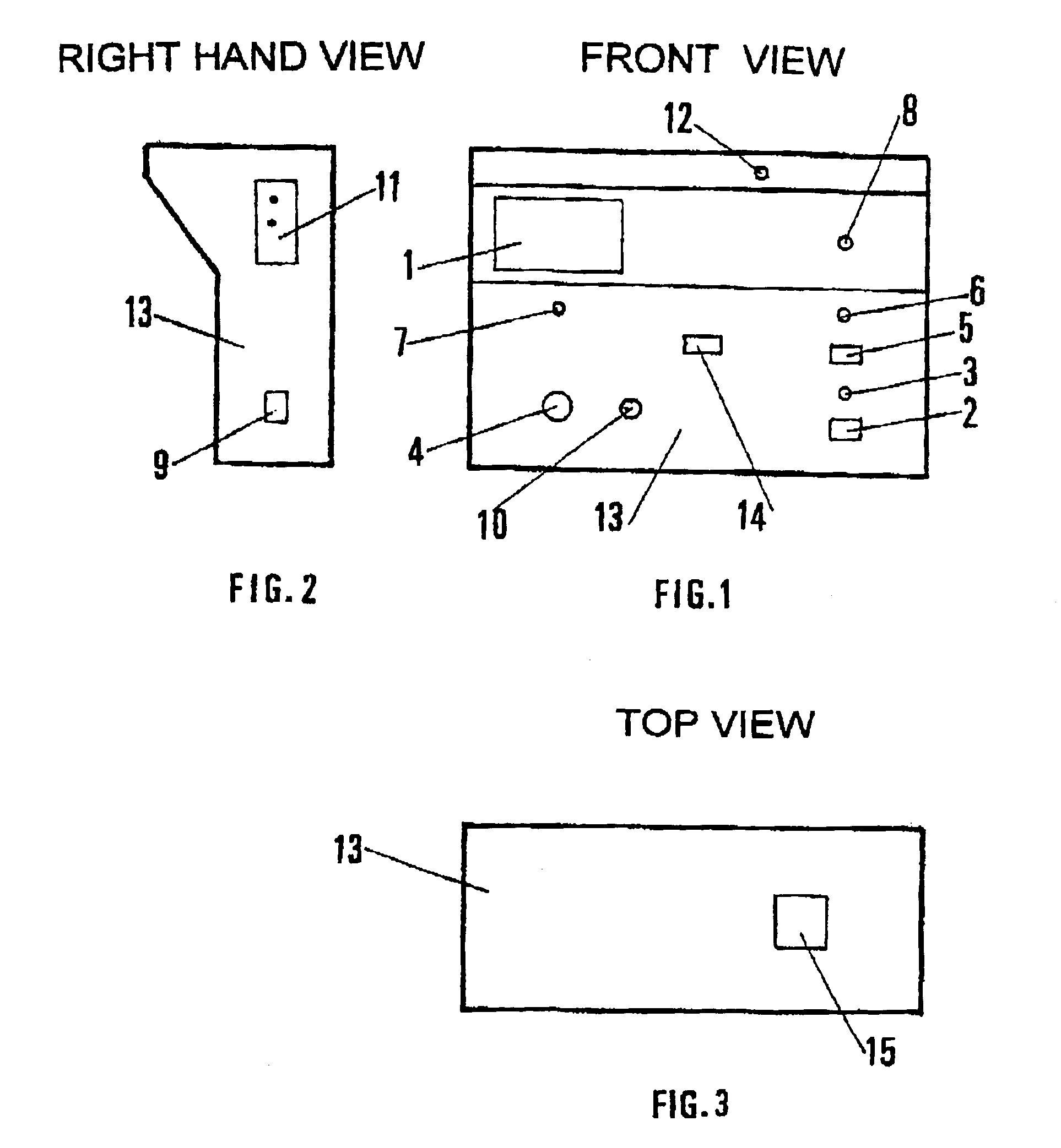
[0014]Making reference to these drawings, the following can be seen on the front of the central transmitter box 13 represented in FIG. 1: a programmable clock (1), a pushbutton “alarm” (2) and its electroluminescent indicator LED (3), the microphone (4) for the voice / sound detection and its potentiometer (10) for adjustment of the microphone, a reversing switch (5) to switch the clock (1) and the voice / sound detector (4), a pushbutton (lit up =active) (14) to activate or deactivate the presence detector(s), a bicolor electroluminescent LED (6) that indicates the state of charge of the battery of the portable vibrating-receiver, a bicolor LED (7) (green=charged / red=discharged) to indicate the state of charge of the transmitter(s) battery for the presence detectors and central transmitter, a green mains LED (8), an antenna (12). On the side of the invention's central transmitter box represented in FIG. 2, there is a housing (11) with two golden and fool proofed contacts, which are use...


PUM


Abstract

The invention concerns transmitters and a portable receiver-buzzer with programmable triggering, hand-, voice-/sound- and pulse-operated, for remotely warning one or several persons. The inventive device consists of a receiver-buzzer case (16), a presence-detecting (23), telephone jack (30), entrance door (36), central transmitter housing (13) transmitting a coded signal to the reciever (20) triggering the motor-buzzer (21) and light-emitting diode (19). In the central transmitter housing (13) there are a clock (1), a voice/sound sensor (4), an alarm push-button (2), a presence detector push-button (14), a LED sector (8), two battery-controlled LED's (6 and 7), a switch button (5) for clock (1) and voice/sound sensor (4), an acknowledgement button (9), an alarm LED (2), a housing (11) for charging the receiver (20) battery, a potentiometer (10). The inventive device consists of a receiver-buzzer (16) wherein are a battery (22), a watch (18), three LED's (17), a receiver (20) receiving the coded signals from the transmitter triggering the buzzer (21). The device, by virtue of its functions, is designed for remotely warning in case of need, emergency or danger, any person equipped with a portable receiver-buzzer.

Description

SUMMARY OF THE INVENTION[0001]The object of this invention is a transmitter vibrating receiver device, which uses the signals sent out by the different transmitters (central, presence detector, telephone plug and front door) to activate the vibrator-motor in the vibrating-receiver box as well as a LED located on the outside of the vibrating-receiver box. This LED discreetly warns the wearer of a portable vibrating-receiver, at a distance, of the occurrence of an urgent situation or danger. At the present time, the existing devices are sound warning systems—which can be awkward in some situations or places—or visual (light flashes), which considerably limit movement and also require sustained, or even constant attention. The device, as defined by this invention, is a solution to these problems. This device, as defined by this invention, consists of a central transmitter box, a “presence detection” box, a telephone plug box, and a front door box (operating on a 220 VAG 50 / 60 Hz supply...

Claims


Application Information

Patent Timeline
Patent Type & Authority Patents(United States)
IPC IPC(8): G08B6/00G08B21/00G08B25/01G08B21/02
CPCG08B6/00G08B21/0208G08B21/0216G08B21/0227G08B25/016
Inventor BELLONE, RAYMONDBELLONE, ALEXIA
Owner BELLONE RAYMOND
Why Eureka
Try Eureka