Electrode structure of EC mirror

a technology of electrochromic mirrors and electrochromic plates, applied in the field of electrochromic mirror electrochromic plate electrochromic plate electrochromic plate electrochromic plate electrochromic plate electrochromic plate electrochromic plate electrochromic plate electrochromic plate electrochromic plate electrochromic plate electrochromic plate electrochromic plate electrochromic plate electrochromic plate electrochromic plate electrochromic plate electrochromic plate electrochromic plate electrochromic plate electrochromic plate electrochromic plate electro

Inactive Publication Date: 2005-09-27
MURAKAMI CORP +1
View PDF5 Cites 33 Cited by
  • Summary
  • Abstract
  • Description
  • Claims
  • Application Information

AI Technical Summary

Benefits of technology

[0015]When the clip of such a configuration is used by being attached to an EC element in such a way as to catch a led-out electrode thereof, the contact area and the contact length between the conductive surface and the clip can be increased because one of the side pieces, which is placed at the side of the conductive surface, is formed in a planar shape in such a manner as to be able to be in planar and intimate contact with the conductive surface. Moreover, poor contact between the conductive surface and the clip can be prevented from being caused owing to the infiltration of a sealing resin into gap therebetween.
[0016]Fu

Problems solved by technology

Furthermore, the lead-out electrode is difficult to damage

Method used


Image

  • Electrode structure of EC mirror
  • Electrode structure of EC mirror
  • Electrode structure of EC mirror

Examples


Embodiment Construction

[0022]An embodiment of the invention is described hereinbelow in more detail with reference to the accompanying drawings.

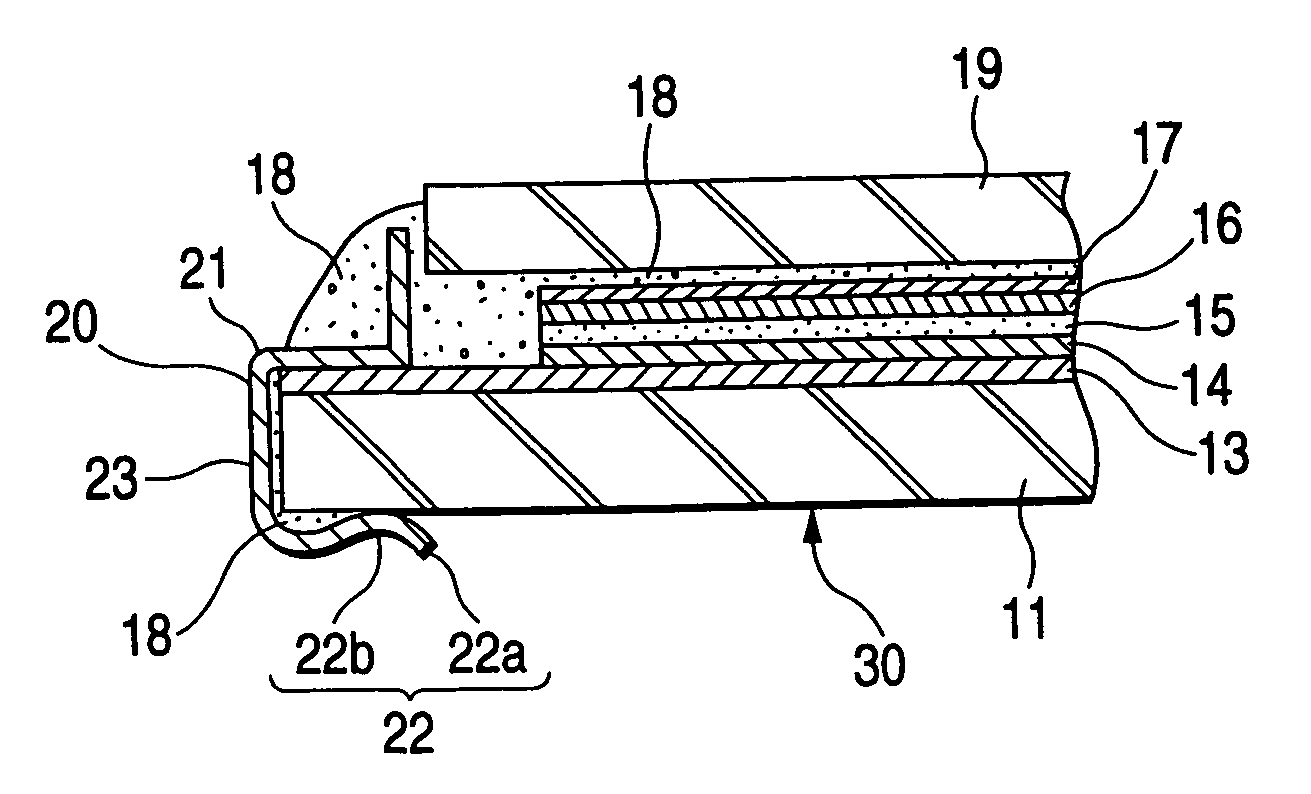
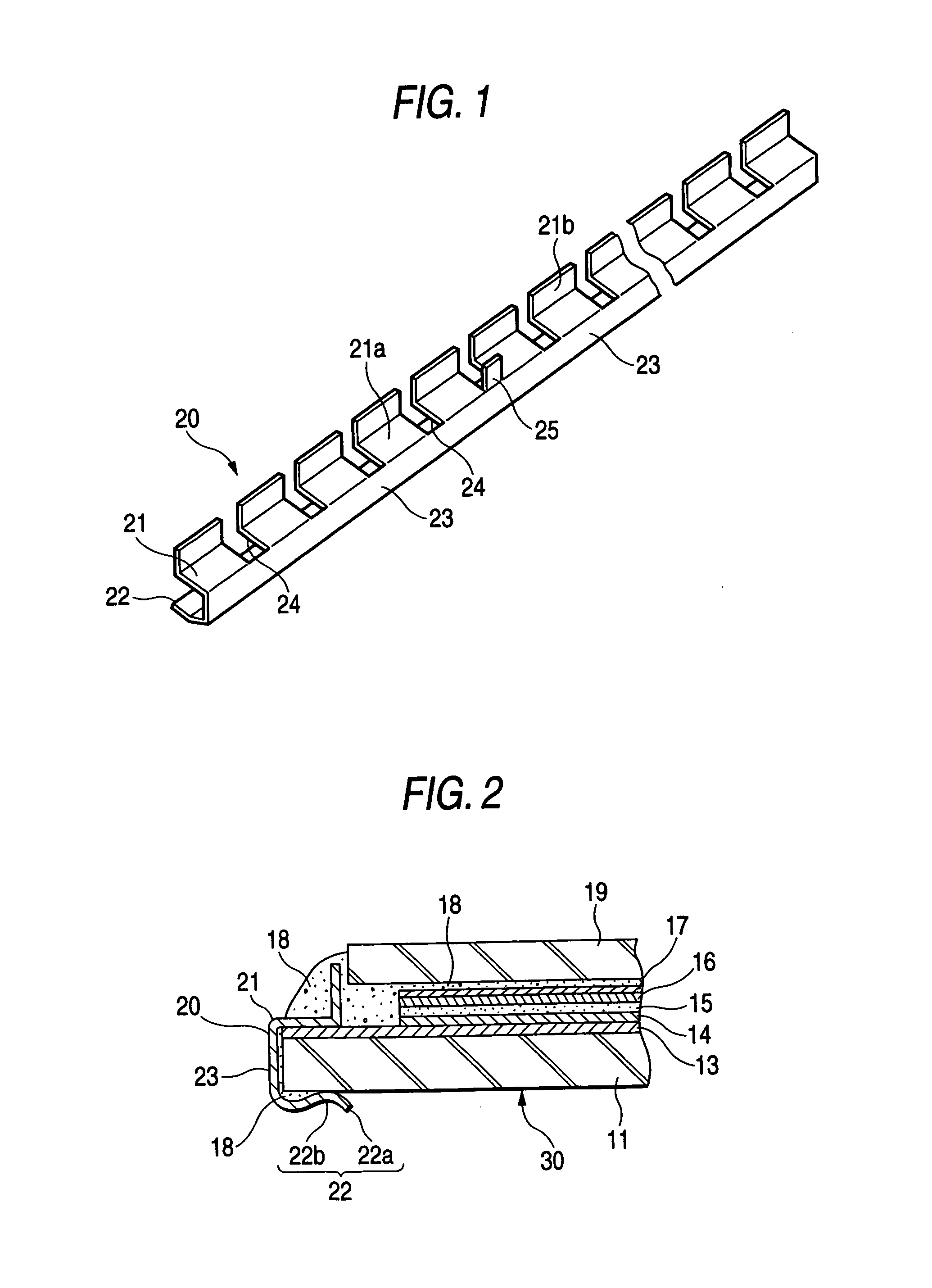
[0023]FIG. 1 is a perspective view illustrating an electrically conductive metallic clip 20. FIG. 2 is an enlarged sectional view illustrating an electrode portion of an EC mirror 30, to which the electrically conductive metallic clip is attached, and showing a state in which a lead-out (electrode) portion a substrate 11 is caught by the clip 20.

[0024]In FIG. 2, reference numeral 11 designates a transparent substrate constituted by a glass plate and so forth, and formed in a convex surface shape. Reference numeral 13 denotes a lower transparent electrically conductive film serving as a first electrode, which is formed on the top surface of the transparent substrate 11. For example, ITO or SnO2 is employed as the material of the film 13. Furthermore, a first coloring layer 14 made of IRTOF and so forth, a solid electrolyte layer 15, a second coloring layer 16 made ...


PUM


Abstract

An electrically conductive metallic clip used for lead-out electrodes of an EC mirror has all-shaped section. One of an opposed side pieces of the clip is disposed at the side of an electrically conductive film and is formed in a planar shape. The other side piece disposed at the side of a glass substrate is configured in a curved shape and has a terminal that is outwardly round-opened. A central portion of the other side piece is formed in a convex shape so that an opening thereof is narrowed. When a sealing resin expands, an occurrence of poor contact between a lead-out electrode portion and the clip is prevented. Moreover, good workability for attaching the clip to the substrate is realized. Furthermore, the lead-out electrode is prevented from being damaged. Additionally, the clip is prevented from being deformed when the clip is fitted onto the substrate.

Description

TECHNICAL FIELD[0001]This invention relates to an electrode structure of an electrochromic mirror (hereunder referred to as an EC mirror) in which a lead-out electrode of an EC element is caught by an electrically conductive metallic clip.BACKGROUND ART[0002]A phenomenon, in which application of a voltage to a material causes an oxidation-reduction reaction, so that reversible colorization or decolorization of a material occurs, is referred to as electrochromism. An electrochromic element (hereunder referred to as an EC element) designed to use a material exhibiting such a phenomenon and to cause the colorization and decolorization of the material by voltage operation is utilized in the fields of a display device and a light control device.[0003]Meanwhile, EC elements include the liquid type and the solid type. The solid type EC elements excel in visibility, safety, and durability and are suitably used for automotive mirrors (for example, outside mirrors, inside mirrors, and door mi...

Claims


Application Information

Patent Timeline
IPC IPC(8): G02F1/01G02F1/153G02F1/155B60R1/04G02F1/15
CPCG02F1/153G02F1/155G02F1/161
Inventor TERADA, YOSHIYUKIMOCHIZUKA, TAKUO
Owner MURAKAMI CORP
Why Eureka
Try Eureka