Telecommunications switch/server

a technology of switch and server, applied in the direction of electrical apparatus construction details, electrical apparatus casings/cabinets/drawers, support structure mounting, etc., can solve the problems of increasing the down time of system operations that rely on the switch, consuming time and effort,

Inactive Publication Date: 2005-09-27
DIALOGIC INC
View PDF12 Cites 25 Cited by
  • Summary
  • Abstract
  • Description
  • Claims
  • Application Information

AI Technical Summary

Benefits of technology

[0008]Yet another object of the invention is to provide a telecommunications switch / server all of whose active components can easily be replaced in the field without disconnecting any cables at the rear of the switch.
[0009]A further object of the invention is to provide a switch of this type which includes a special redundancy connector enabling the switch to be connected to a companion or standby switch in a redundant system so that upon failure detection in the primary unit, all telephone and data traffic is automatically switched to the standby unit without any user intervention or re-cabling so that there is no interruption of system operations.
[0015]As a result of its unique two-section design, the present switch has many advantages. For example upon failure, all active components of the switch may be replaced without removing the mounting hardware from the cabinet or rack in which the switch is mounted and without removing any cables connected to the switch. Also when the switch is part of a redundant system, when the switch fails, all of the active components of the switch may be replaced without interrupting any active service or system operations. That is, in such a redundant system, upon failure detection, all telephony and data traffic are automatically switched to the redundant or standby unit without any user intervention or recabling.

Problems solved by technology

The prior switches of this type are disadvantaged in that if the switch fails for one reason or another, the entire switch chassis has to be unfastened and removed from its cabinet or rack so that the switch can be inspected and repaired or replaced.
Since the rear of the cabinet or rack containing the switch is often in a difficult-to-access location, this can be a tedious and time-consuming task.
In other words, unless special care is taken during such replacement, there is a likelihood that one or more cables will be plugged into the wrong port at the rear of the new switch, all of which increases the down time of the system operations that rely on the switch.

Method used


Image

  • Telecommunications switch/server
  • Telecommunications switch/server
  • Telecommunications switch/server

Examples


Embodiment Construction

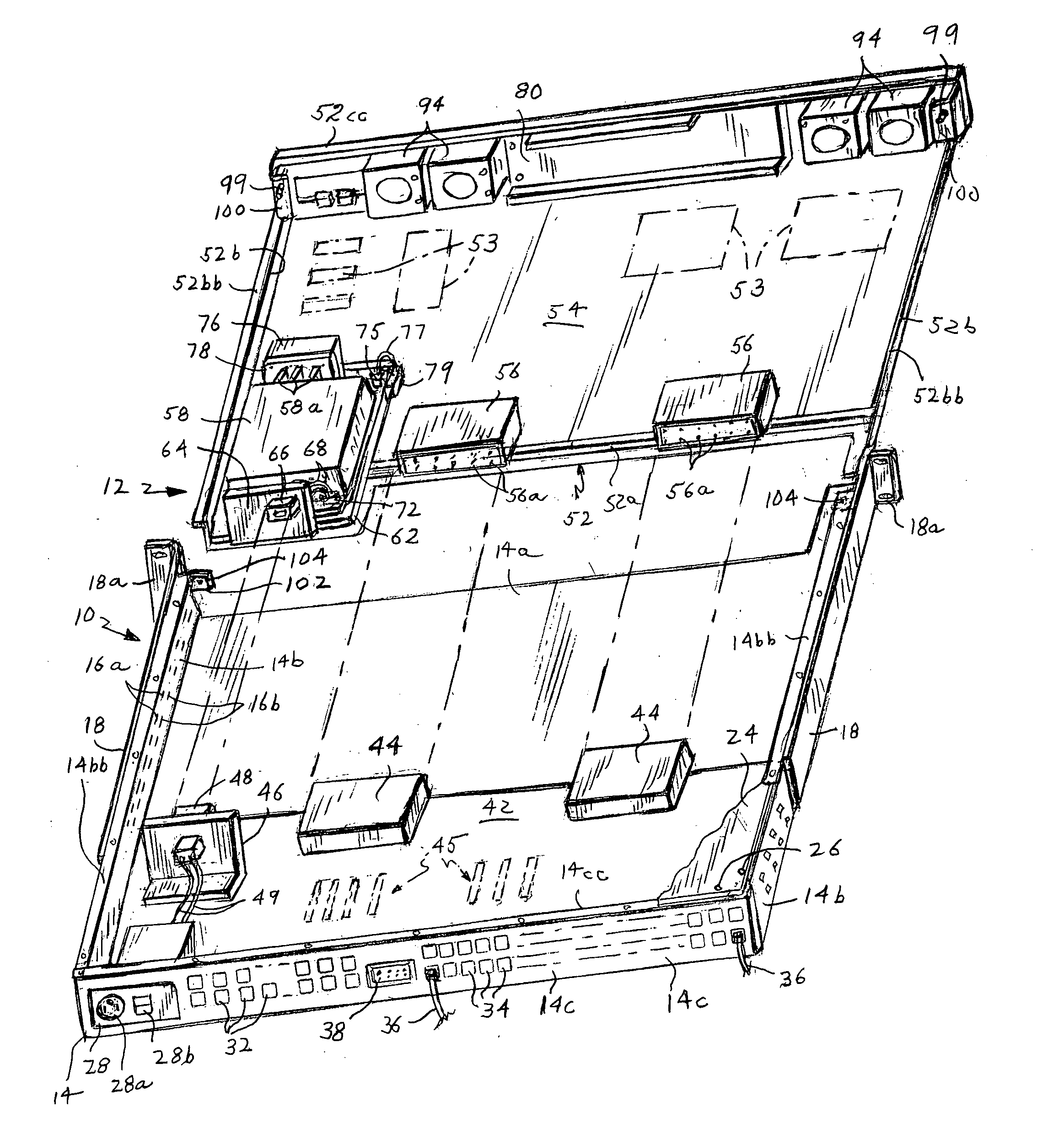
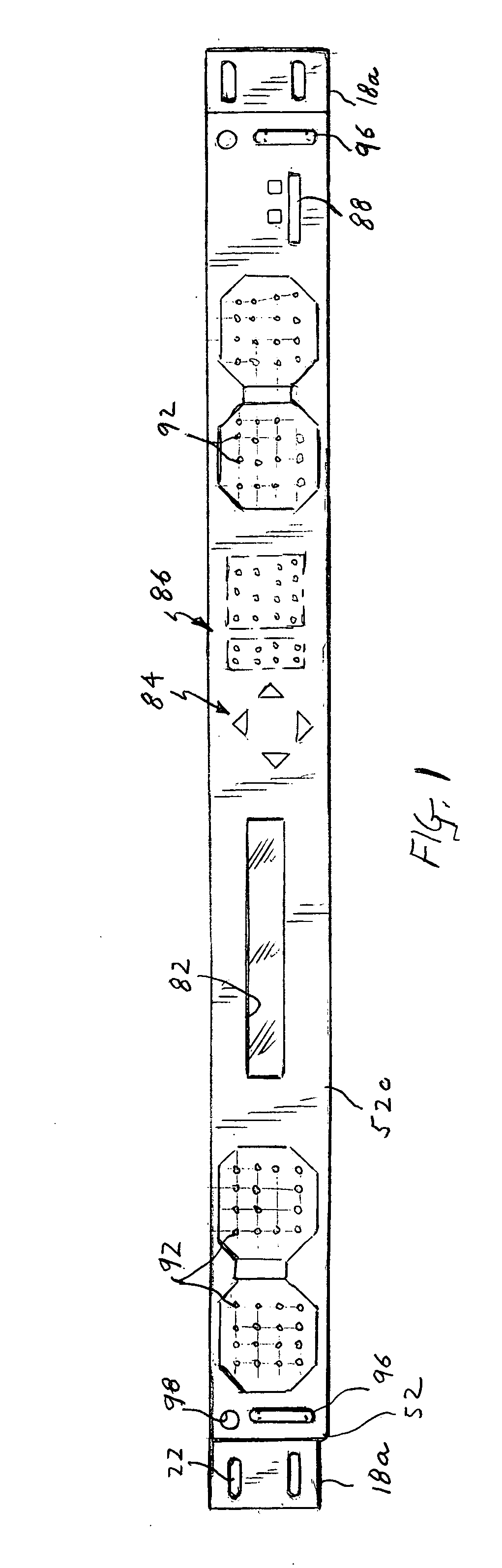
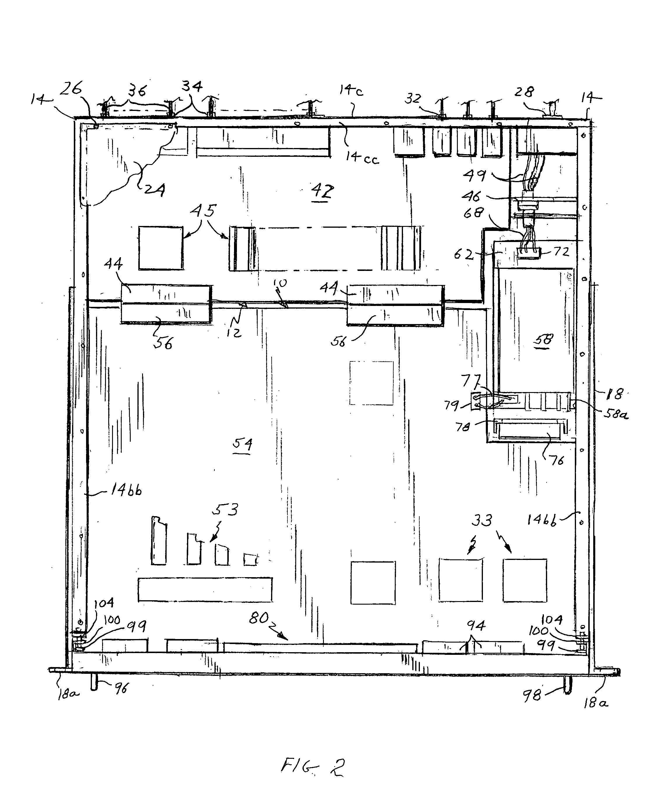
[0022]Referring to FIGS. 1 to 3 of the drawings, the present switch / server comprises a passive section shown generally at 10 and an active section or tray 12 adapted to dock to section 10. As we shall see, section 10 contains only the physical interfaces to the data and telephony networks and power input to the switch, while tray 12 carries all of the active components of the switch such as processors, memories, line interface units, power supply, etc. When section 12 is docked to section 10, all of the necessary connections are made between the two sections to enable the switch to perform all of its functions.

[0023]The connections to the switch are all made at ports at the rear of the passive section 10. Therefore, that section may be permanently mounted in a rack or cabinet. In other words, it is not intended to be a field replaceable unit. The active section or tray 12, on the other hand, is designed to slide into and dock to section 10. Therefore, if a switch malfunction should ...


PUM


Abstract

The switch has a passive section and an active section or tray that may be docked to the passive section. The passive section contains only the physical interfaces to the switch's external data and telephony networks and power input. It is not intended to be a field replaceable unit and is therefore intended to be mounted in a rack system with all of the power and communications cables attached thereto. The telephony and data ports are routed from the passive section to the active section via connectors on the two sections as well as to a redundancy connector on the passive section that may be physically connected by a cable to a slave unit in a redundant application. The active section or tray contains all of the active components of the switch and is inserted via guides into the passive section. The tray is considered a field replaceable unit and can be inserted into and extracted from the passive section while the system is powered up and operational. As a result of its unique two-section design, the present switch has several advantages. For example upon failure, all active components of the system may be replaced without removing the mounting hardware from the rack in which the switch is mounted and without removing any cables connected to the switch. Also when the switch is part of a redundant system, when the switch fails, all of the active components of the switch may be replaced without interrupting system operations.

Description

[0001]This invention relates to telephony and data communication apparatus. It relates especially to an improved telecommunications switch / server.BACKGROUND OF THE INVENTION[0002]A telecommunications switch / server is used to route message traffic over a network. Conventionally, it comprises a chassis or housing containing a single printed circuit motherboard or back plane which supports and interconnects a multiplicity of electrical components that enable the switch to perform its functions, e.g. processors, memories, line interface units, etc. The chassis usually also includes a front panel to which is mounted various switches, indicators and displays that enable one to control and monitor the operation of the switch / server. Electrical connections to and from the switch are made by way of a multiplicity of data and telephony ports mounted in a rear wall of the chassis. Cables plugged into ports at the rear of the chassis connect the switch to outside lines and to other units compri...

Claims


Application Information

Patent Timeline
Patent Type & Authority Patents(United States)
IPC IPC(8): H01R12/16H01R12/00H05K7/16H05K7/00H04M3/12H04Q1/02H05K7/14
CPCH05K7/1487H04Q1/023H04Q1/03H04M3/12H04Q2201/10H04Q2201/12
Inventor DECESARE, JOHN R.ALLEN, JAMES F.LACEY, KATHLEEN M.FAUNCE, JESSE A.CORSINI, PETER HYNES
Owner DIALOGIC INC
Why Eureka
Try Eureka