Optimal shaft balance using integer programming to handle discrete adjustment

a discrete adjustment and integer programming technology, applied in the field of mechanical system adjustment, can solve the problems of unflyable helicopter flying, unflyable helicopter flying, and unacceptable vibration, and achieve the effect of reducing vibration, reducing vibration, and minimizing the number of weights added

Inactive Publication Date: 2005-09-27
SIMMONDS PRECISION PRODS
View PDF14 Cites 21 Cited by
  • Summary
  • Abstract
  • Description
  • Claims
  • Application Information

AI Technical Summary

Benefits of technology

[0008]According to the present invention, determining a balance adjustment for a mechanical component includes measuring an initial vibration of the component, determining if the initial vibration is greater than a predetermined value, and, if the initial vibration is greater than the predetermined value, determining an adjustment by choosing a best adjustment for each possible location for adjustments. Choosing the best adjustment may include choosing an adjustment that causes a lower amount of vibration than adjustments not chosen. Choosing the best adjustment may include choosing an adjustment that reduces the vibration to an acceptable level and minimizes the number of weights that are added. Measuring an initial vibration may include using an accelerometer. Measuring an initial vibration may include using conditioning electronics in connection with the accelerometer. The predetermined value may be 0.01 ips. Determining an adjustment may also include, following measuring an initial vibration of the component, indicating a mechanical fault in response to the initial vibration containing a significant frequency component other than a frequency component at a rotation rate of the component. A significant component may correspond to a magnitude of at least 25% of a magnitude of the frequency component at the rotation rate of the component. Determining an adjustment may include setting an initial proposed adjustment, setting a first pointer to point to a first location, setting a second pointer to point to a first weight, iterating the second pointer through each of the weights and updating the proposed adjustment when a new weight causes a decrease in calculated vibrations, and iterating the first pointer through each of the locations and performing the iteration of the second pointer at each location. Determining an adjustment may include setting an initial proposed adjustment, setting a first pointer to point to a first weight, setting a second pointer to point to a first location, iterating the second pointer through each of the location and updating the proposed adjustment when a new weight causes a decrease in calculated vibrations, and iterating the first pointer through each of the weights and performing the iteration of the second pointer for each weight. The component may be a shaft and all of the possible locations for an adjustment may be symmetrical about a circumference at an end of the shaft. All of the possible locations for an adjustment may be at a constant radius about a circumference at an end of the shaft. A first set of the possible locations for an adjustment may be at a first radius about a circumference at an end of the shaft and a second set of the possible locations for an adjustment may be at a second radius about a circumference at an end of the shaft. All of the possible locations for an adjustment may be non-symmetrical about a circumference at an end of the shaft.

Problems solved by technology

In some cases, imbalance of the shaft may cause unacceptable vibrations.
For example, in a helicopter system with many high speed shafts, a vibration of two ips (inches per second) renders the helicopter unflyable.
Even shaft vibration as slow as ½ ips may make flying in a helicopter uncomfortable.
However, it is usually difficult to determine manually how much needs to be added to each location.
Using trial and error is impractical because, in the first place, determining an effective adjustment using trial and error requires restarting the machine and remeasuring the vibrations each time an adjustment is made and, in the second place, the number the combinations may make trial error prohibitive.
However, even if the vibrations are measured by the computer, it may not be possible to provide an exact counteracting weight since the adjusting weights are discrete amounts provided at discrete locations whereas the vibration could be any amount at any location on the shaft.
In addition, a computational trial and error method may be prohibitive with a computer because, just as with the manual trial error method, the number of combinations may so large that it would be prohibitive to have a computer do calculations for all the possible combinations.

Method used


Image

  • Optimal shaft balance using integer programming to handle discrete adjustment
  • Optimal shaft balance using integer programming to handle discrete adjustment
  • Optimal shaft balance using integer programming to handle discrete adjustment

Examples


Embodiment Construction

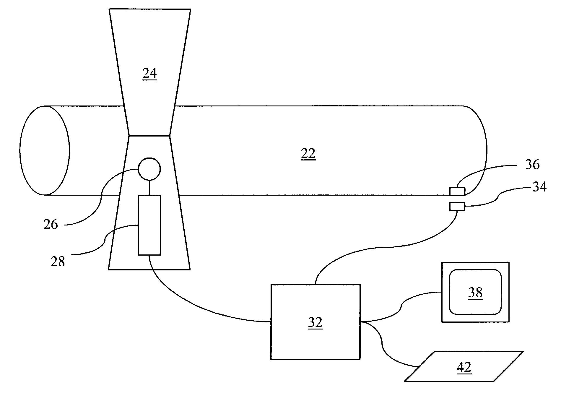
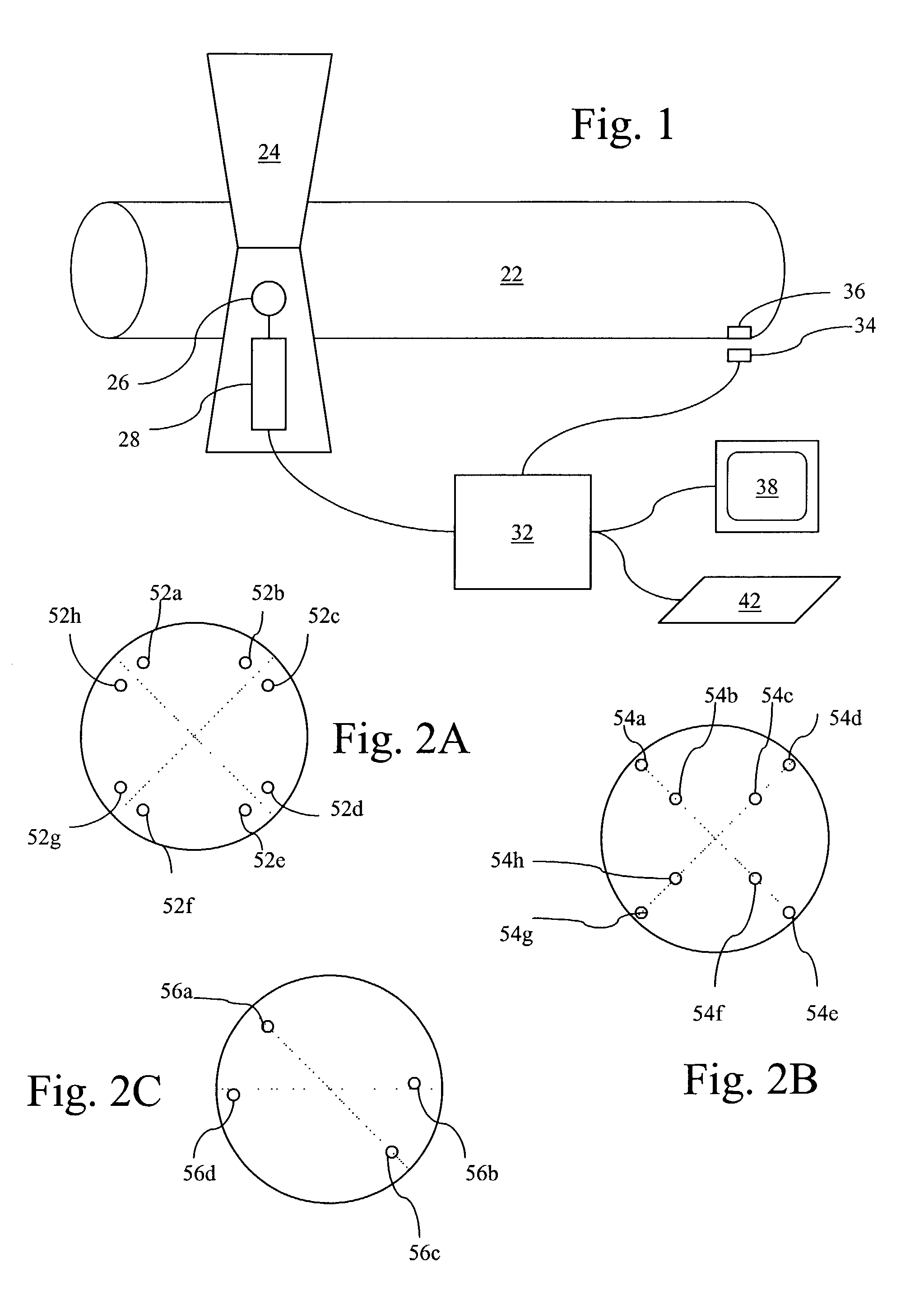
[0016]Referring to FIG. 1, a diagram 20 illustrates a system for measuring and suggesting adjustments to correct vibrations of a rotating shaft 22. The shaft 22 may be part of a larger system such as a mechanical system for a helicopter or another system that includes rotating shafts.

[0017]The shaft 22 may be supported by one or more bearings such as a pillow bearing 24 shown in FIG. 1. Vibration of the shaft 22 may be measured by an accelerometer 26 mounted on the bearing 24. The accelerometer 26 may measure vibration of the shaft 22 (in g's) and provide an electronic output signal proportional to the vibrations experienced by the accelerometer 26. The electronic output signal of the accelerometer 26 may be provided to optional signal conditioning electronics 28 that process / condition the electronic signal and perhaps even digitize the signal. The output of the conditioning electronics 28 may be provided to a processor 32 which receives the signal from the accelerometer 26 and cond...


PUM


Abstract

Determining a shaft balance adjustment includes measuring an initial vibration of the shaft, determining if the initial vibration is greater than a predetermined value, and, if the initial vibration is greater than the predetermined value, determining an adjustment by choosing a best adjustment for each possible location for adjustments. Choosing the best adjustment may include choosing an adjustment that causes a lower amount of vibration than adjustments not chosen. Measuring an initial vibration may include using an accelerometer. Measuring an initial vibration may include using conditioning electronics in connection with the accelerometer. The predetermined value may be 0.01 ips.

Description

BACKGROUND OF THE INVENTION[0001]1. Technical Field[0002]This application relates to the field of adjusting mechanical systems, and more particularly to the field of measuring vibration and using the measurement to provide suggested adjustments to reduce the vibration.[0003]2. Description of Related Art[0004]Mechanical system often contain a plurality of shafts that rotate at relatively high speeds. In some cases, imbalance of the shaft may cause unacceptable vibrations. For example, in a helicopter system with many high speed shafts, a vibration of two ips (inches per second) renders the helicopter unflyable. Even shaft vibration as slow as ½ ips may make flying in a helicopter uncomfortable. Thus, it is desirable to be able to eliminate or at least reduce vibrations caused by shaft imbalance.[0005]In some cases, shafts are provided with a provision for inserting weights at the end thereof in the form of bolts and / or washers. There may be a number of possible bolts of different fix...

Claims


Application Information

Patent Timeline
Patent Type & Authority Patents(United States)
IPC IPC(8): F16F15/00F16F15/32G01M1/24G01M1/00G01M1/36
CPCG01M1/24G01M1/36
Inventor BECHHOEFER, ERIC ROBERT
Owner SIMMONDS PRECISION PRODS
Why Eureka
Try Eureka