
Method for facilitating development and testing of relational database application software

a technology for relational database applications and software, applied in relational databases, program control, instruments, etc., can solve the problems of varying degrees of complexity of processes, large data storage capacity, complex databases, etc., and achieve the effect of facilitating development and testing

Inactive Publication Date: 2005-09-27
FRESCHE SOLUTIONS INC
View PDF1 Cites 33 Cited by
  • Summary
  • Abstract
  • Description
  • Claims
  • Application Information

AI Technical Summary

Benefits of technology

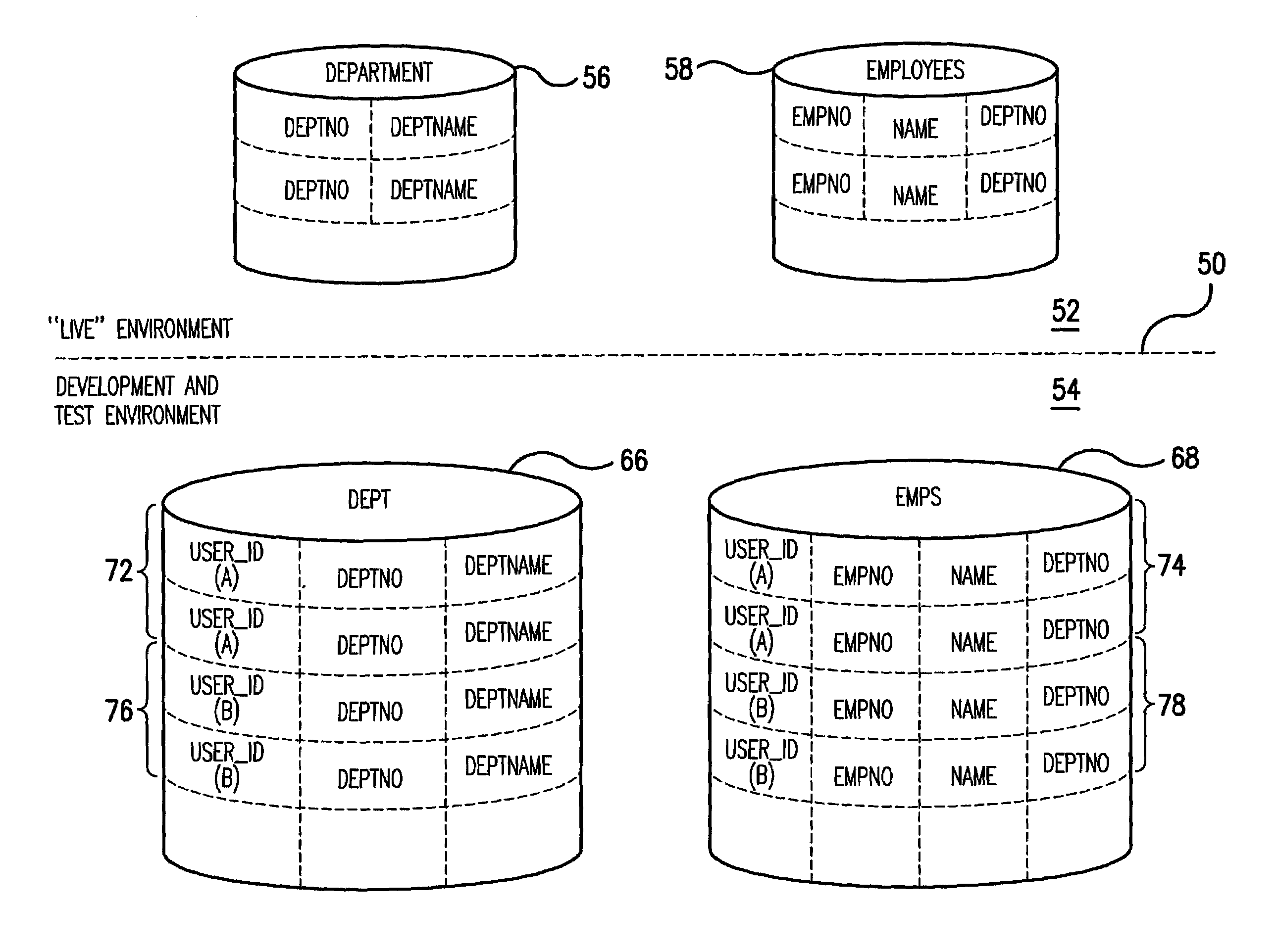
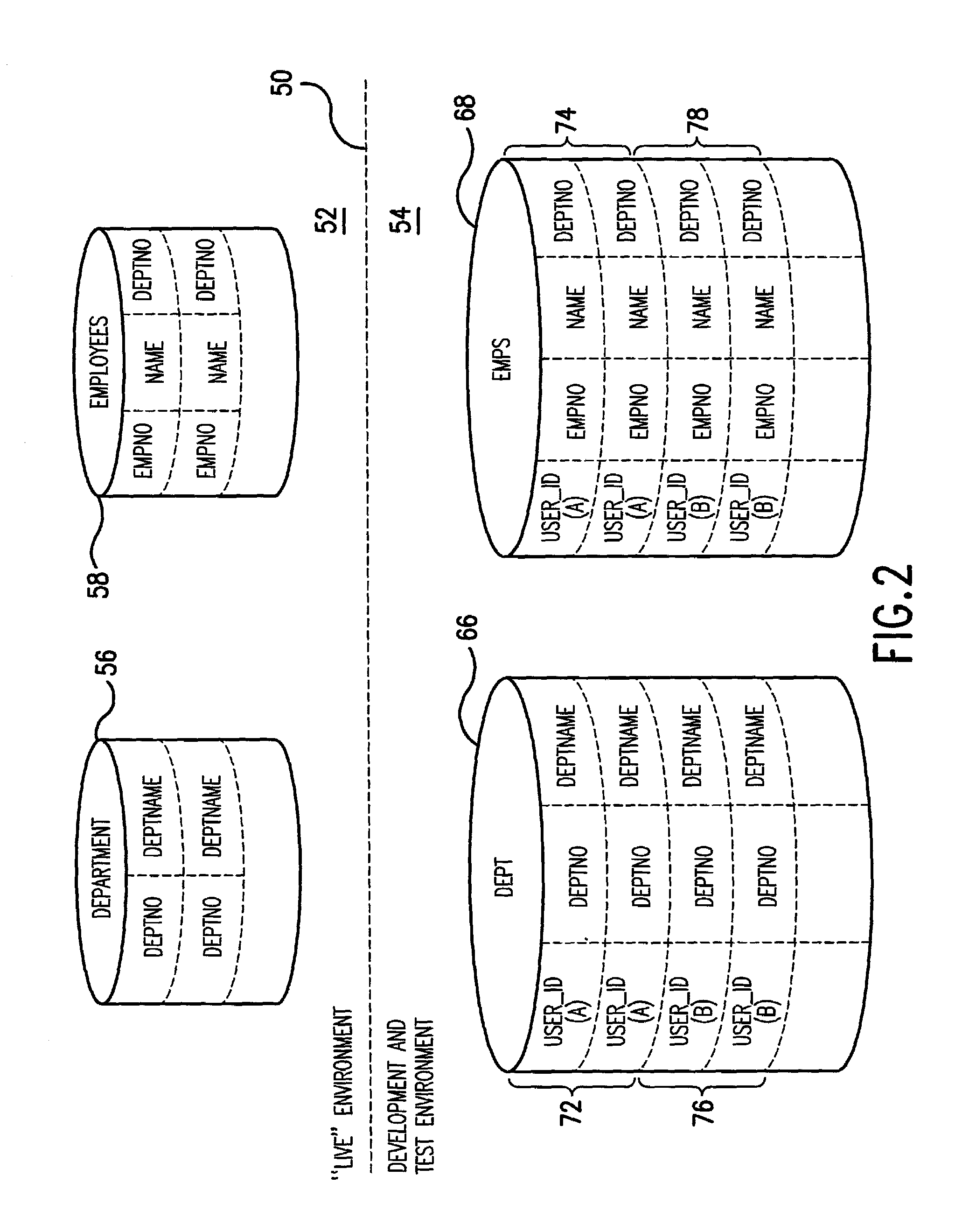
[0025]An exemplary embodiment of the invention provides a method for facilitating the development and testing, by a plurality of individual user entities, of a relational database application program which includes a plurality of Data Manipulation Language statements, which runs under a database management system and which accesses original database tables organized as rows of defined columns. For each original database table, Data Definition Language statements are employed at least a first time to create a corresponding new table. Within the new table are defined the same columns that are defined in the original database table. The new table includes an additional column that is defined to include a User Identification. For each original database table, Data Definition Language statements are also employed at least a first time to define a view created having the same name and column definitions as the corresponding original database table, where the view selects only the rows in the new table in which the User Identification matches a particular user entity. For each particular user entity, access is allowed to the view (created by a match of the User Identification with the particular user entity) for executing Data Manipulation Language statements of the application program, including statements to insert rows, without modification of the statements of the application program other than for purposes of developing and testing functionality of the application program.

Problems solved by technology

A database can be very complex, involving, as noted above, hundreds of tables, and requiring a large data storage capacity when “live,” for example, several terabytes.
Providing an application development and testing environment in which a plurality of user entities access the database, as a practical matter, presents a number of challenging demands, if conflicts are to be avoided.
Each stage of the testing process has varying degrees of complexities and demands on coordinating testing efforts.
Clearly there are conflicts.
A very limited amount of coordination is necessary for unit testing.
In the context of the invention, it can be difficult to keep track of the test data necessary to repeat the tests and re-establish the test data, especially when tests require isolation or a predefined order to the testing schedule.
Testing a report program while testing the update program may produce unpredictable results.
These can be time consuming and frustrating questions to answer.
Allowing more than one group of testers to perform these tests in the same environment on shared data is neither practical nor advised.
Different test activities can adversely affect one another.
Testing in this way is very error-prone and requires extensive coordination activity that slows project progress and can impede, if not prevent, parallel testing.
Individual unit tests also have the problem of determining whether the program functioned as expected.
Using a database management system like DB2 can pose additional demands.
The very facilities that guarantee production data integrity make testing more difficult.
Moreover, while the load utility is executing, the tables are unavailable for other testing work.
Referential integrity constraints can cause additional consideration as to how the data is saved and loaded, or even which tables are required for testing.
Even so, errors can occur in programs that will occasionally cause updates to data that is not intended.
This avoids DB2 load and lock contention problems entirely, but it can be an expensive alternative.
Even with the availability of DB2 alter and migrate tools, this alternative becomes very time consuming for database administrators (humans).
Another risk of this solution is not properly making a table change to all environments.
This could result in application program code being developed against an outdated table definition.
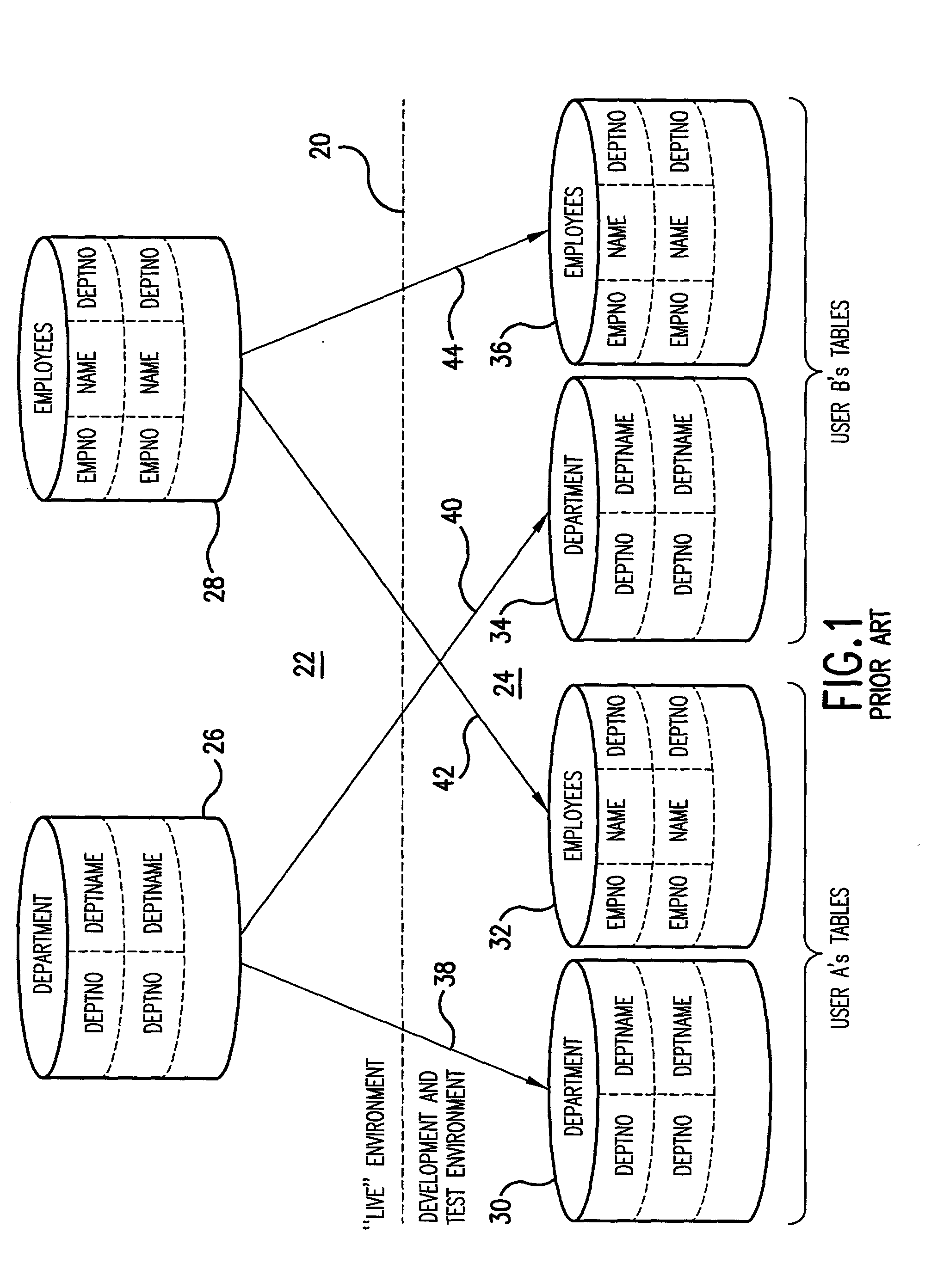
Unfortunately, it requires modification of application program source code, and these modifications can be quite extensive.
While an improvement to other prior art approaches, this particular approach still has drawbacks.

Method used


Image

  • Method for facilitating development and testing of relational database application software
  • Method for facilitating development and testing of relational database application software
  • Method for facilitating development and testing of relational database application software

Examples


example 1

[0032]

CREATE TABLE TS3EMP.DEPARTMENT(DEPTNOCHAR(3)  NOT NULL,DEPTNANEVARCHAR (38)NOT NULL,MGRNOCHAR (6),ADMRDEPTCHAR (3)NOT NULL,LOCATIONCHAR (16),PRIMARY KEY (DEPTNO) ) IN TDBEMP01.S01 CCSID EBCDIC;CREATE UNIQUE INDEX TS3EMP.XDEPT1 ON TS3EMP.DEPARTMENT(DEPTNO  ASC) USING STOGROUP TEMPIX01PRIQTY 12 ERASE NOCLUSTERBUFFERPOOL BP0 CLOSE NO;

[0033]In the foregoing EXAMPLE 1, the DEPARTMENT table created, unlike the simplified example of FIG. 1, actually has five columns defined, namely, DEPTNO, DEPTNAME, MGRNO, ADMRDEPT and LOCATION. The primary key is based on the DEPTNO column only. Also, the creator TS3EMP is specified. (Table names are unique by their creator (sometimes referred to as owner) and their name. (The name before the dot is the creator and the name after the dot is the name of the table.) Usually, but not always, the creator is used for multiple versions of the same table. So, in a development and test environment, one could have for example one hundred invoice tables all ...

example 2

[0044]

CREATE TABLE TS3EMP.DEPT(DEPTNOCHAR (3)NOT NULL,SQL—USERCHAR (08)NOT NULL WITHDEFAULTCURRENT SQLID,DEPTNANEVARCHAR (36)NOT NULL,MGRNOCHAR (6),ADMRDEPTCHAR (3)NOT NULL,LOCATIONCHAR (16),PRIMARY KEY (SQL—USER,DEPTNO) ) IN TDBEMP01.S01 CCSID EBCDIC;CREATE UNIQUE INDEX TS3EMP.XDEPT1 ON TS3EMP.DEPT(SQL—USER, DEPTNO ASC) USING STOGROUP TEMPIX01PRIQTY 12 ERASE NOCLUSTERBUFFERPOOL BP0 CLOSE NO;COMMENT ON TABLE TS3EMP.DEPT IS ‘DEPARTMENT’;CREATE VIEW TS3EMP.DEPARTMENT (DEPTNO,DEPTNAME,MGRNO,ADMRDEPT,LOCATION) AS SELECTDEPTNO,DEPTNAME,MGRNO,ADMRDEPT,LOCATIONFROM TS3EMP.DEPTWHERE SQL—USER = CURRENT SQLIDWITH CHECK OPTION;

[0045]In the foregoing EXAMPLE 2, the new DEPT database table created, unlike the simplified example of FIG. 2, actually has six columns defined, namely, DEPTNO, SQL—USER, DEPTNAME, MGRNO, ADMRDEPT and LOCATION. Thus, compared to the prior art example of EXAMPLE 1, there is an additional column named SQL—USER. The primary key is based on a combination of the SQL—USER and...

example 3

[0057]

CREATE TABLE TS3EMP.DEPT(DEPTNOCHAR (3)NOT NULL,DEPTNAMEVARCHAR (36)NOT NULL,MGRNOCHAR (6),ADMRDEPTCHAR (3)NOT NULL,LOCATIONCHAR (16),PRIMARY KEY (DEPTNO) ) IN TDBEMP01.S01 CCSID EBCDIC;CREATE UNIQUE INDEX TS3EMP.XDEPT1 ON TS3EMP.DEPT(DEPTNO  ASC) USING STOGROUP TEMPIX01PRIQTY 12 ERASE NOCLUSTERBUFFERPOOL BP0 CLOSE NO;CREATE VIEW TS3EMP.DEPARTMENT(DEPTNO,DEPTNANE,MGRNO,ADMRDEPT,LOCATION) AS SELECTDEPTNO,DEPTNANE,MGRNO,ADMRDEPT,LOCATIONFROM TS3EMP.DEPT;

[0058]With either the first or second approach, an application program (using DML) developed using the view is guaranteed to work the same when applied to the original database tables. Modification of program source code is not required.

[0059]In view of the foregoing, it will be appreciated that, during development and testing of a database application program by a plurality of individual user entities, each slice is completely isolated from the activities of other user entities, and this isolation is achieved without modificatio...


PUM


Abstract

A method for allowing individual user entities access to tables in a database, such as a DB2 database, in an isolated manner, that is, without interfering with each other. For each original database table, DDL statements are employed to create a new table. Within the new table are defined the same columns that are defined in the original database table, as well as an additional column that includes a User Identification. A view is created having the same name and column definitions as the original database table, where the view selects only the rows in the new table in which the User Identification matches a particular user entity. For each particular user entity, access is allowed to the view for executing DML statements of the application program without modification of the DML statements of the application program other than for purposes of developing and testing functionality of the application program.

Description

BACKGROUND OF THE INVENTION[0001]The invention relates generally to relational database application software development and testing and, more particularly, to a method for allowing individual user entities (e.g. individual users or user groups) access to tables in the database in an isolated manner, that is, without interfering with each other.[0002]Databases are computerized information storage and retrieval systems that are essential for the operations of many businesses. A database manager, also known as a database management system (DBMS), is a complex and sophisticated computer program that provides a variety of tools for defining, manipulating data in, controlling access to and otherwise managing the database in a variety of ways. A relational database management system (RDBMS) uses relational techniques for storing and retrieving data organized into tables which consist (conceptually) of rows and columns of data. The manner in which data is physically stored in the database ...

Claims


Application Information

Patent Timeline
Patent Type & Authority Patents(United States)
IPC IPC(8): G06F9/44G06F17/30
CPCG06F11/3688G06F17/30418G06F17/30595G06F16/2445G06F16/284
Inventor LOZINS, NEAL N.
Owner FRESCHE SOLUTIONS INC
Learn More