Valve with damping element

a technology of damping element and valve body, which is applied in the direction of valve operating means/releasing devices, mechanical equipment, machines/engines, etc., can solve the problems of noise development, pressure disturbance in the fluid system of the cooling system, and complicated mutual decoupling of the two parts of the displacement rod, so as to reduce the noise, reduce the structural parts and components, and the effect of speeding up the installation

a technology of damping element and valve body, which is applied in the direction of valve operating means/releasing devices, mechanical equipment, machines/engines, etc., can solve the problems of noise development, pressure disturbance in the fluid system of the cooling system, and complicated mutual decoupling of the two parts of the displacement rod, so as to reduce the noise, reduce the structural parts and components, and the effect of speeding up the installation

US6951330B2Inactive Publication Date: 2005-10-04ROBERT BOSCH GMBH

Image

  • Valve with damping element
  • Valve with damping element
  • Valve with damping element

Examples


Embodiment Construction

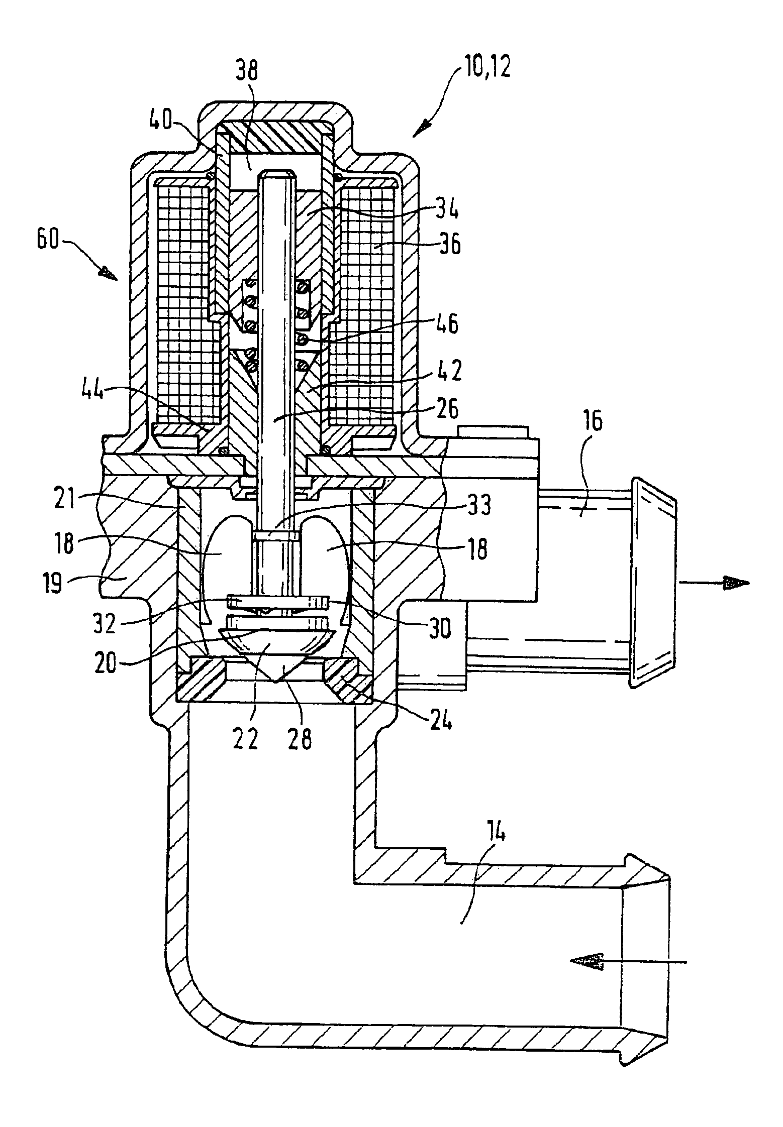
[0027]The valve 10 of the invention, in the embodiment of a magnet valve 12 of FIG. 1, has an inlet conduit 14 and an outlet conduit 16, which communicate with one another via a valve chamber 18. The valve chamber 18 is formed by a valve chamber unit 21 inserted into the valve housing 19. Between the conduits 14 and 16, a valve member 20 is provided, which is disposed movably in the valve chamber 18 and which cooperates, via an elastic valve cone 22, with a valve seat 24 of the valve chamber 18. The valve seat 24, in the exemplary embodiment of FIG. 1, is embodied as an elastic ring that defines the valve chamber 18 relative to the inlet conduit 14.

[0028]Because of the elastic valve seat 24, the valve cone 22 of the valve member 20 need not necessarily also be elastic, in this exemplary embodiment.

[0029]The valve member 20 is axially displaceably supported on a displacement rod 26, and on the end of the displacement rod 26 toward the valve seat 24, it is secured on the displacement ...


PUM


Abstract

The invention relates to a valve, in particular for a fluid-regulated heating and / or cooling system of a motor vehicle, having a valve chamber (18, 218), with at least one inlet conduit (14, 214) and at least one outlet conduit (16, 216) branching off from it, and having a displacement rod (26, 226) movable by an actuator, and having at least one valve member (20, 220), which is located on the displacement rod (26, 226) and cooperates with at least one valve seat (24, 224) of the valve chamber (18, 218), and at least one damping element (20, 220) is provided, which slows down the speed of the displacement rod (26, 226) upon closure of the valve (10, 12).According to the invention, it is provided that the at least one damping element (20, 220) simultaneously acts as a valve member (20, 220).

Description

BACKGROUND OF THE INVENTION[0001]The invention is based on a valve for a fluid-regulated heating and / or cooling system of a motor vehicle.[0002]Such valves are known, for instance from fluid-regulated heating and / or cooling systems of motor vehicles. A valve member secured to a displacement rod of the valve regulates the flow between an inlet conduit and at least one outlet conduit. The valve can be triggered for instance as a function of temperatures in the heating and / or cooling system of the motor vehicle, or in the passenger compartment. Valves of this type at present primarily still have an electromagnetic actuator, which closes the valve by means of an excited magnet coil, causing the actuator to act on an armature connected to the displacement rod of the valve. A disadvantage of this type of valve is that the actuation of the actuator causes an abrupt closure and thus leads to pressure disturbances in the fluid system of the cooling system.[0003]The water valves known at pres...

Claims


Application Information

Patent Timeline
04 Oct 2005
Publication
US6951330B2
IPC
F01P7/14; F16K31/06
CPC
F01P7/14; F16K31/0689; F16K31/0696; F01P2007/146; F16K47/01
Inventors
HESS, JUERGEN; REEB, GEORG