
Stabilizer for a motor vehicle

a technology for stabilizing motor vehicles and stabilizers, applied in vehicle components, resilient suspensions, interconnection systems, etc., can solve the problems of slippage between the two stabilizer parts, insufficient twist angle, and single stabilizers that cannot accept increased loads

Inactive Publication Date: 2005-10-04
ZF LEMFOERDER METALLWAREN AG +1
View PDF20 Cites 34 Cited by
  • Summary
  • Abstract
  • Description
  • Claims
  • Application Information

AI Technical Summary

Benefits of technology

[0014]Therefore, it is an object of the invention to develop a stabilizer of the kind recited, which eliminates the recited disadvantages of the state-of-the-art and which automatically closes in a fail-safe-situation and which does not automatically separate in a coupled state.
[0017]The invention eliminates the recited disadvantages of the state of the art. A particular advantage results therefrom that the two radial catches are disposed on a common plane and also remain in a common plane in each operating state and that only the adjustment piston with its locking elements is disposed axially shiftable. A play free and slippage free connection of the two stabilizer parts occurs thereby in the coupled state. No further force transfer planes, which would shorten the effective length of the stabilizer parts, exist as a result of the arrangement of the two radial catches in the common plane.

Problems solved by technology

Single part stabilizers react however to different loads either too soft or too hard, which is disadvantageous for the driving comfort and single part stabilizers cannot accept increased loads.
The twist angle however is insufficient in case of road unevenness problems acting extremely different onto the wheels, such as they occur cross-country.
In addition a slippage exists between the two stabilizer parts because of the rubber spring element, which operates disadvantageously onto the driving behavior in case of a straight driving and planar road.
Such friction clutches are not safe, since also a slippage of the clutch cannot be excluded in the closed position and since an unlimited twist angle is possible in the separated position under an exclusion of the stabilizer function.
This is a safety risk.

Method used


Image

  • Stabilizer for a motor vehicle
  • Stabilizer for a motor vehicle
  • Stabilizer for a motor vehicle

Examples


Embodiment Construction

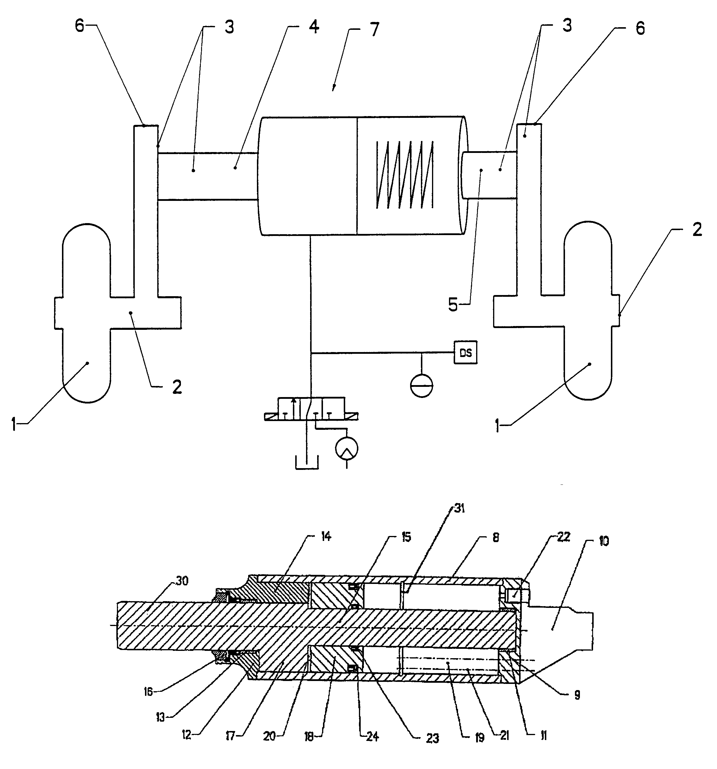
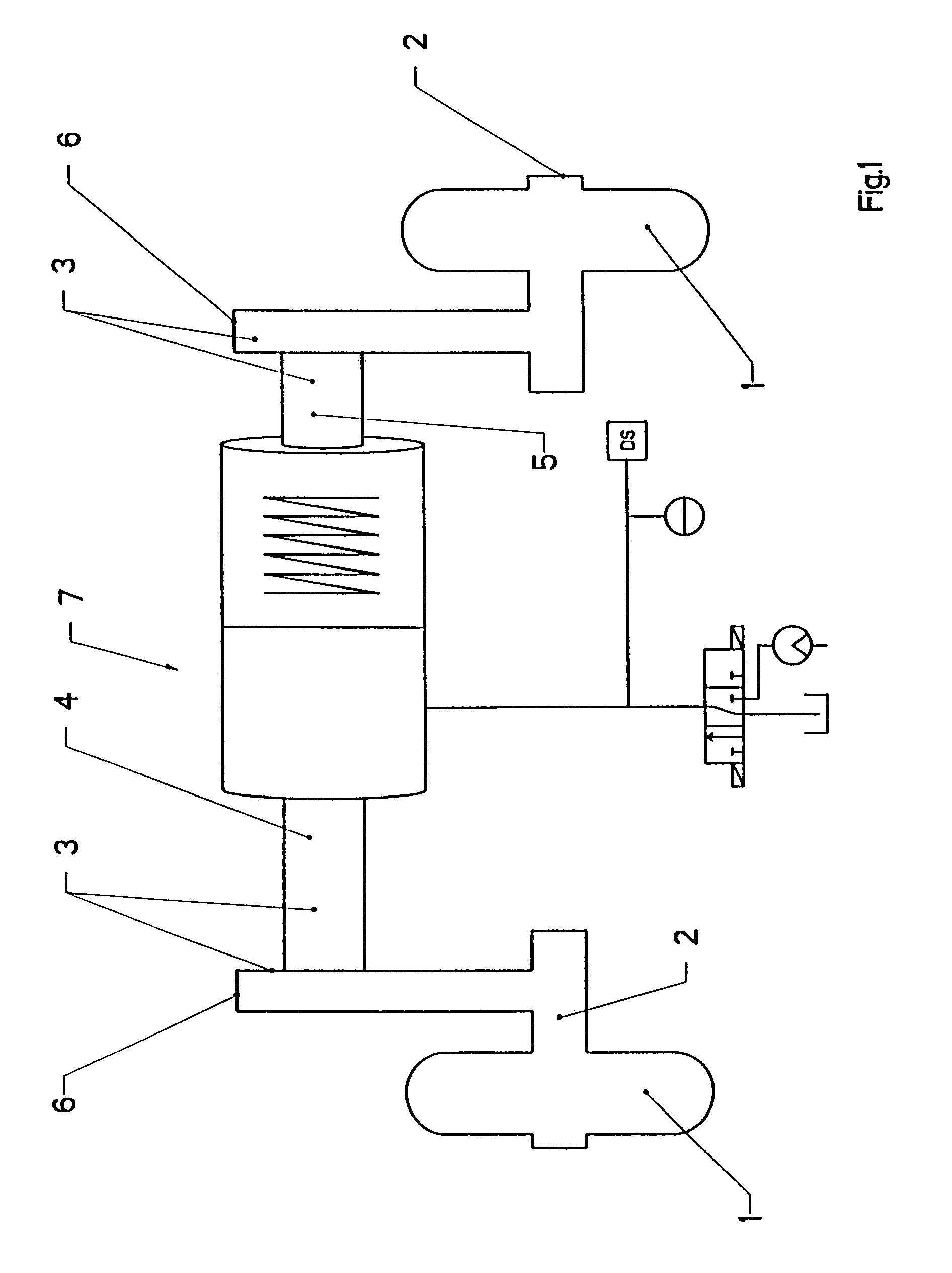
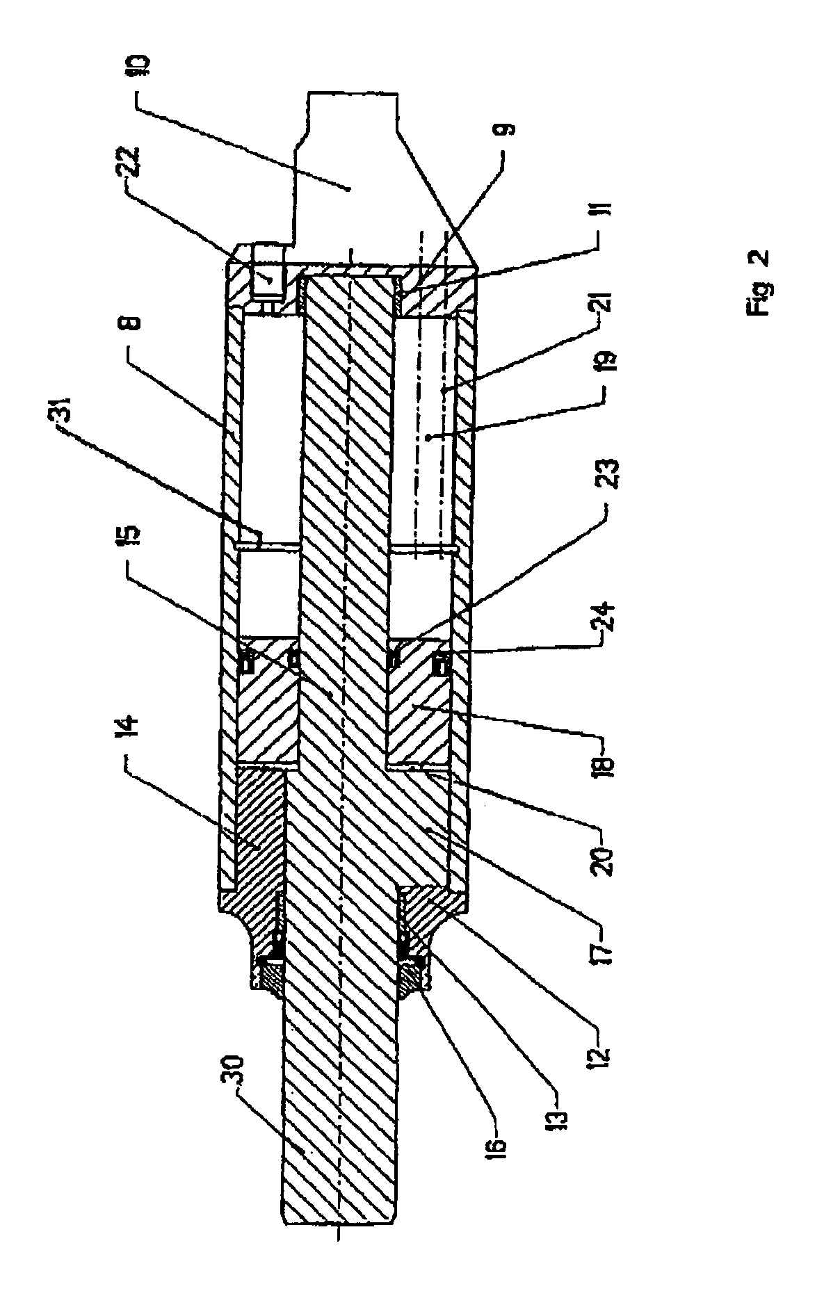
[0024]Each axle of a motor vehicle comprises according to FIG. 1 in principle the two wheels 1 and one supporting axle 2 carrying the two wheels 1. A subdivided stabilizer 3 with its two stabilizer parts 4 and 5 is disposed parallel to the axle 2, wherein each stabilizer part 4, 5 is connected with a wheel suspension not illustrated of the corresponding wheel 1 and on the other hand to the vehicle body for support position 6. A clutch 7 is disposed between the two stabilizer parts 4 and 5, wherein the clutch 7 connects to each other or separates from each other the two stabilizer parts 4, 5 to a straight continuous stabilizer 30 through a gearing. The connected stabilizer 3 is adjusted in its dimensioning and in its material properties to receive torsion forces introduced through the wheels 1 and to build up corresponding counter forces. These forces are thereby not transferred or at least dampened onto the vehicle body.

[0025]The clutch 7 is constructed axially switchable and shape ...


PUM


Abstract

The invention relates to a stabilizer for a motor vehicle. Known one-piece stabilizers are designed either solely for operation in road traffic or solely for off-road operation. Two-piece stabilizers that comprise an engaging and disengaging clutch have disadvantages regarding quality and safety. The invention provides a clutch, drivers (14, 17) of which form at least two adjustable gaps in the peripheral direction. The gaps can be filled by at least two locking elements (25) that can be displaced to a certain extent. The locking elements (25) and said drivers (14, 17) are constantly in positive engagement with one another in the peripheral direction and are adjusted to one another in such a manner that the locking elements (25) and the drivers (14, 17) are interlocked without play in the locked final position and that they can be rotated towards one another across a limited angle in the unlocked final position.

Description

CROSS-REFERENCE TO RELATED APPLICATIONS[0001](not applicable)STATEMENT REGARDING FEDERALLY SPONSORED RESEARCH OR DEVELOPMENT[0002](not applicable)INCORPORATION-BY-REFERENCE OF MATERIAL SUBMITTED ON A COMPACT DISC[0003](See 37 CFR 1.52(e)(5) and MPEP 608.05. Computer program listings (37 CFR 1.96(c)), “Sequence Listings” (37 CFR 1.821(c)), and tables having more than 50 pages of text are permitted to be submitted on compact discs.) or REFERENCE TO A “MICROFICHE APPENDIX” (See MPEP § 608.05(a). “Microfiche Appendices” were accepted by the Office until Mar. 1, 2001.)[0004](not applicable)BACKGROUND OF THE INVENTION[0005](1) Field of the Invention[0006]The invention relates to a stabilizer with the features of the preamble of claim 1.[0007](2) Description of Related Art including information disclosed under 37 CFR 1.97 and 1.98.[0008]Such stabilizers are employed in motor vehicle technology.[0009]In principle a stabilizer working according to the torsion bar principle is coordinated to ...

Claims


Application Information

Patent Timeline
IPC IPC(8): B60G21/00B60G21/055
CPCB60G21/0553B60G21/0556
Inventor BEETZ, STEFANREICHEL, KLAUS
Owner ZF LEMFOERDER METALLWAREN AG
Learn More