Motor with axially moveable bearing member

a bearing member and axial movement technology, applied in the direction of sliding contact bearings, elastic bearings, mechanical devices, etc., can solve the problems of low precision, low precision of pivot bearing members b>6/b>, and generation of motor noise, etc., to achieve the effect of high precision and quick formation

Inactive Publication Date: 2005-10-04
SANKYO SEIKI MFG CO LTD
View PDF5 Cites 8 Cited by
  • Summary
  • Abstract
  • Description
  • Claims
  • Application Information

AI Technical Summary

Benefits of technology

[0011]The present invention relates to a motor in which its bearing holder for retaining a bearing member can be readily and high accurately formed, and a fixing structure for retaining the bearing holder can be miniaturized.
[0013]In accordance with an embodiment of the present invention, a motor has a bearing member and a bearing holder that retains the bearing member, wherein the bearing holder is formed from a sintered compact member. Because the bearing holder is formed from a sintered compact member, the bearing holder that may have a complex structure can be readily and highly accurately formed. In particular, because the bearing holder is formed from a sintered compact member, a mounting hole provided in the bearing holder for retaining the bearing member has a highly accurate inner circumferential wall surface, such that the bearing member retained by the bearing holder can be maintained in a good sliding state, and the bearing member can be readily and highly accurately positioned in the axial direction.
[0014]Moreover, since the bearing holder is formed from a sintered compact member, the bearing holder may be affixed in position by welding. For example, in a motor having a rotor section and a stator section that is disposed opposite the rotor section, the bearing holder may be affixed to a yoke of the stator section by welding. This simplifies the fixing structure of the bearing holder, and reduces the overall size of the motor.
[0016]As a result, the rigidity of the flexible supporting member can be maintained and the number of mounting sections can be reduced. Accordingly, the flexible supporting member can be reduced in size, and the bearing holder can also be reduced in size.

Problems solved by technology

However, when the bearing holder 8 is formed from a resin member, an inner wall surface of the mounting hole 8a for receiving the pivot bearing member 6 may not always be finished with a high precision due to various factors such as shrinkage of the resin member when forming the bearing holder 8 with resin.
As a consequence, the pivot bearing member 6 may not be highly accurately positioned in the axial direction.
The lowered mounting precision of the pivot bearing member 6 not only results in generation of motor noise but also results in a larger fixing structure for retaining the bearing holder 8, which poses a difficulty in miniaturization of the motor.
The mounting hole 8a may have problems in finishing precision in the surface condition, such as, for example, burrs that remain on its inner wall surface.

Method used


Image

  • Motor with axially moveable bearing member
  • Motor with axially moveable bearing member
  • Motor with axially moveable bearing member

Examples


Embodiment Construction

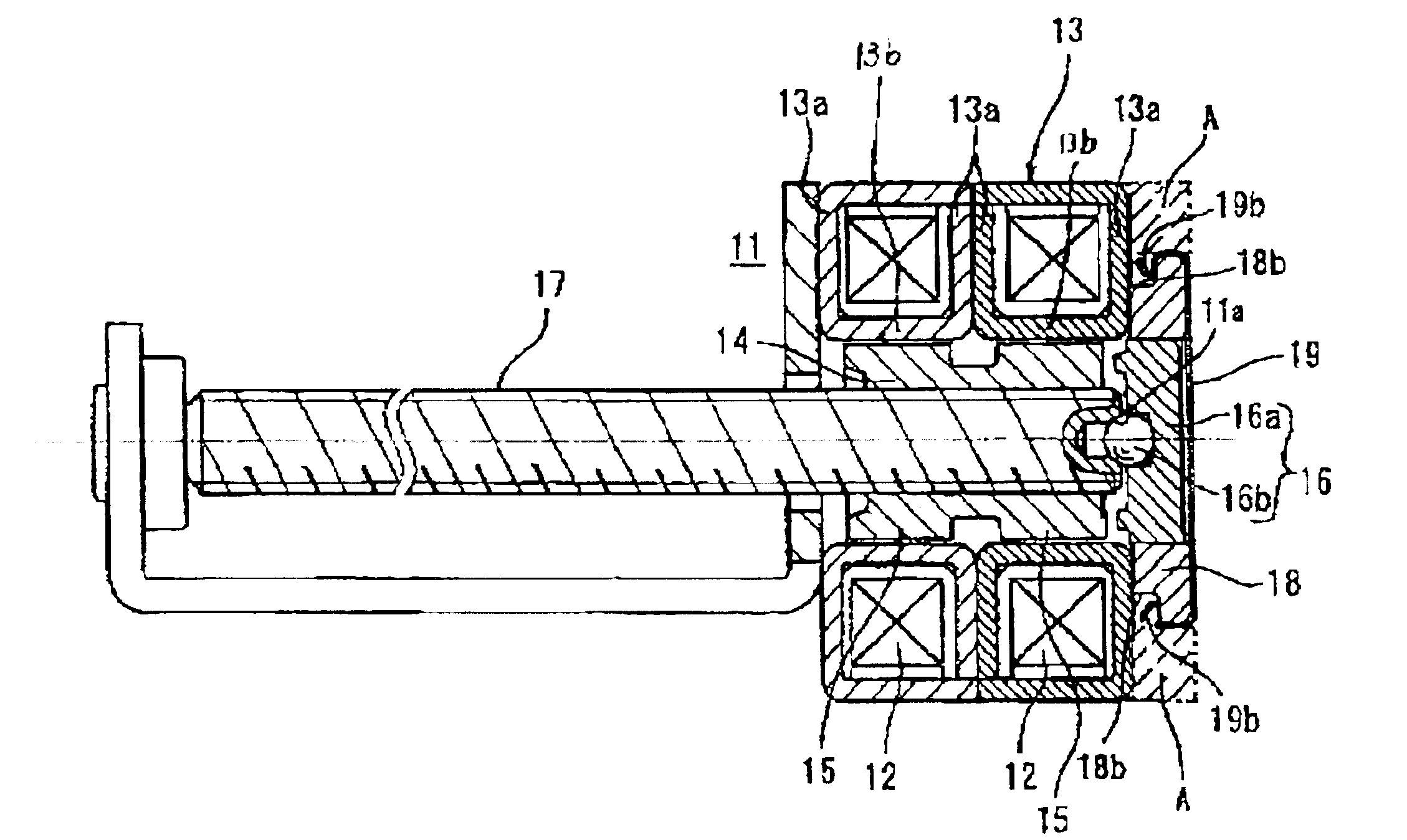
[0027]A PM type stepping motor in accordance with an embodiment of the present invention will be described in detail below with reference to the accompanying drawings.

[0028]A PM type stepping motor shown in FIG. 1 includes a stator unit with a core assembly 13 having a plurality of coils 12 that are wound in a generally cylindrical shape about a rotor shaft 11. The coils 12 are disposed adjacent to each other along an axial direction to form a plurality of phases. A rotor section 14 is mounted on the rotor shaft 11 in a center side section of the core assembly 13. A rotor magnet 15 is circularly mounted on an outer circumferential surface of the rotor 14. The rotor magnet 15 is disposed in close proximity to the core assembly 13 in the radial direction.

[0029]The core assembly 13 is provided with retaining yokes 13a that are disposed to sandwich the coils 12 in the axial direction. Plural pole teeth 13b extend in the axial direction from inner end edges of the retaining yokes 13a tha...


PUM


Abstract

A motor includes a rotor section with a rotor shaft having an end section, and a stator section including a yoke section disposed opposite the rotor section. The motor is also equipped with a bearing assembly having a bearing member that includes a main bearing section with a recess section and a ball bearing received in the recess section wherein the ball bearing rotatably support the end section of the rotor shaft, and a bearing holder defining a center through hole that slidably holds the main bearing section of the bearing member in the axial direction, wherein the bearing holder is formed from a sintered compact member.

Description

BACKGROUND OF THE INVENTION[0001]1. Field of the Invention[0002]The present invention relates to a motor equipped with a bearing member mounted on a bearing holder, wherein the bearing member is moveable in an axial direction and immovable in a radial direction.[0003]2. Related Background Art[0004]A motor may be provided with a rotor shaft that is rotatable with a rotor unit in an unitary fashion, wherein end sections of the rotor shaft are rotatably supported by appropriate bearing members. For example, FIG. 5 shows a permanent magnet type (PM type) stepping motor of the type described above. The stepping motor includes a stator unit with a core assembly 3 having a plurality of coils 2 that are wound in a generally cylindrical shape about a rotor shaft 1. The coils 2 are disposed adjacent to each other along an axial direction to form a plurality of phases. A rotor section 4 is mounted on the rotor shaft 1 in a center side section of the core assembly 3 in a manner that the rotor s...

Claims


Application Information

Patent Timeline
Patent Type & Authority Patents(United States)
IPC IPC(8): F16C17/08F16C17/04H02K5/167H02K7/06H02K5/173H02K37/14
CPCF16C17/08H02K7/06H02K7/081Y10S384/902F16C2380/27F16C27/08
Inventor MUTAI, HITOSHIHOSHINA, KENICHI
Owner SANKYO SEIKI MFG CO LTD
Why Eureka
Try Eureka