
High voltage bushing

a high-voltage bushing and cable technology, applied in the direction of cable termination, electric cable installation, cable fitting in presence of gas/oil, etc., can solve the problems of dielectric tube current limit, damage to the surface or destroy the dielectric tube, and associated technical difficulties and expens

Inactive Publication Date: 2005-10-04
NAVY SEC OF THE UNITED STATES +1
View PDF18 Cites 20 Cited by
  • Summary
  • Abstract
  • Description
  • Claims
  • Application Information

AI Technical Summary

Benefits of technology

[0006]A high voltage bushing includes an electrically conductive coupling having an aperture; first and second dielectric tubes mounted to the coupling so that they are coaxially aligned and have first and second ends, respectively; first and second end plates mounted in a fluid tight manner to the first and second ends of the first and second tubes,

Problems solved by technology

Corona is very hot plasma, and over the course of time, it can damage the surface or destroy the dielectric tube.
This approach has been used for 60 Hz high voltage bushings, but the methods used to insulate such floating tubes have associated technical difficulties and expense.
For example, heating of the dielectric used to support the floating tubes in position can limit the temperature rise and hence the current limit of the busing.
Perhaps more importantly, the floating tubes significantly increase the capacitance of the bushing, which is deleterious for RF antenna applications.

Method used


Image

  • High voltage bushing
  • High voltage bushing
  • High voltage bushing

Examples


Embodiment Construction

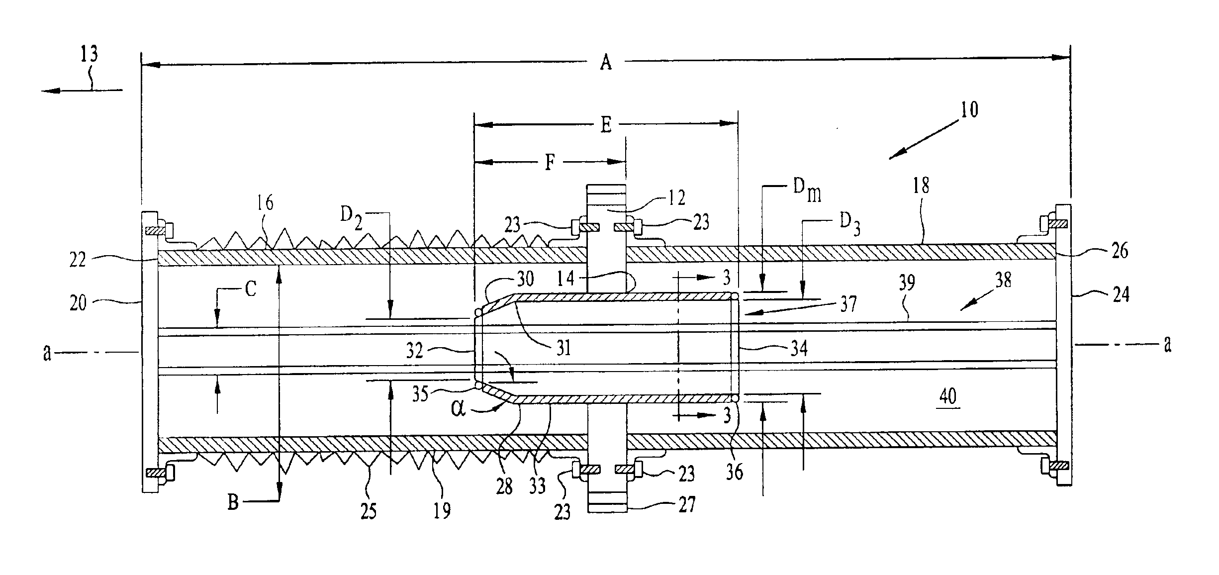
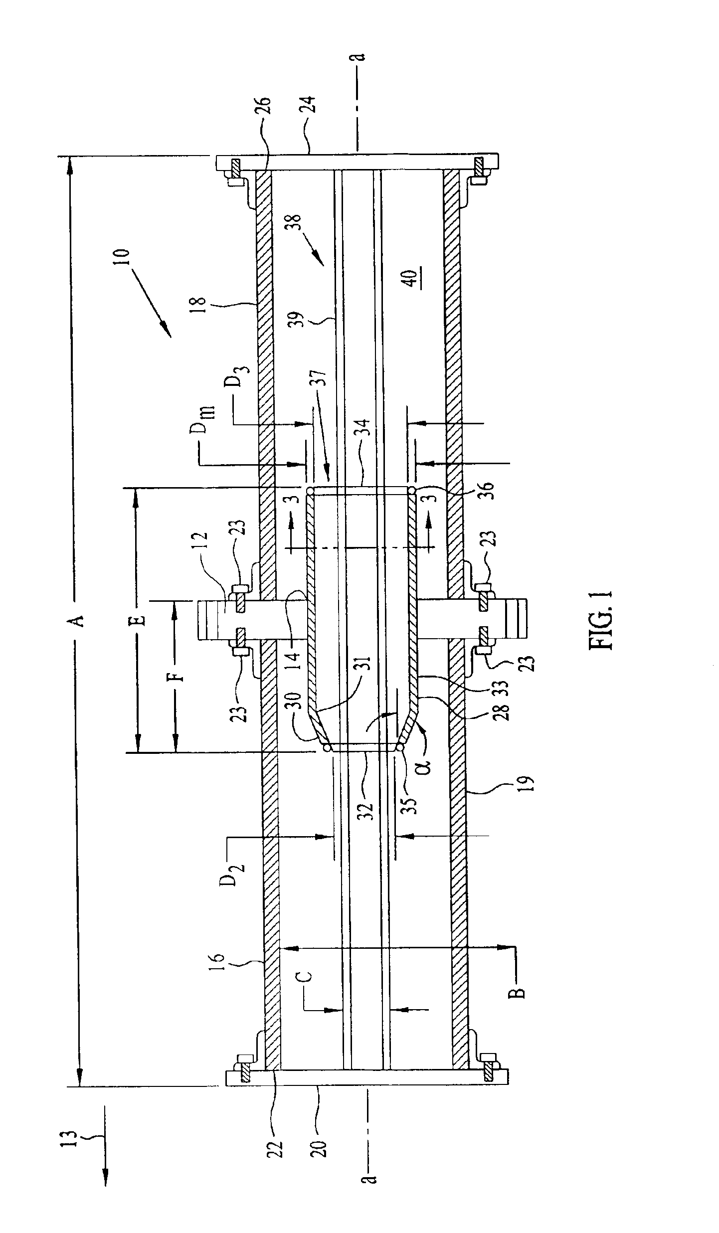
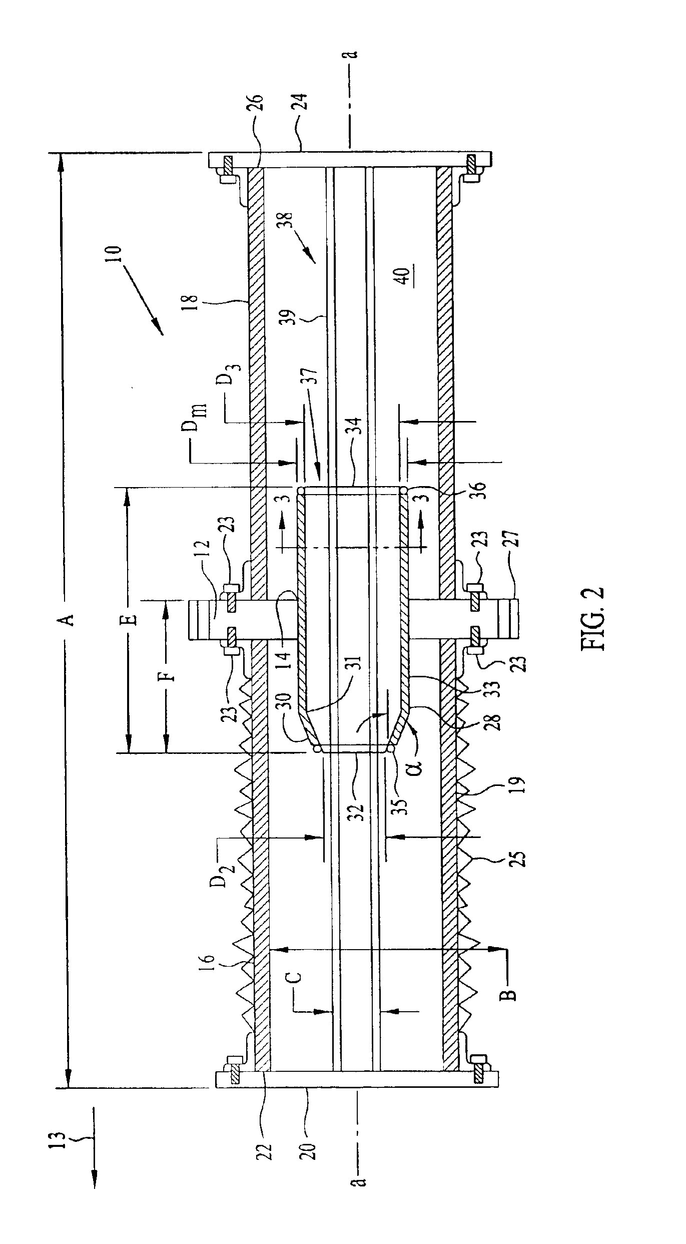
[0011]Referring to FIG. 1, there is shown a high voltage feed-through bushing 10, which may be used, for example, as the high voltage, high current connection to a high power radio broadcast antenna. In one embodiment, arrow 13 points upwardly towards the sky (not shown). Feed-through bushing 10 may carry high voltage and current on center conductor 38 which may be of an electrically conductive material fabricated, for example, from copper, steel, or aluminum tubing. The center conductor 38 may be coated with silver to increase its conductivity in order to reduce conduction losses, thereby allowing more current to be carried. Dielectric tubes 16 and 18 are mounted in coupling 12 so that the tubes are coaxially aligned with each other along axis a—a. In one embodiment, dielectric tubes 16 and 18 may be secured in coupling 12 with fasteners 23, such as bolts 23. Tubes 16 and 18 may be straight or tapered cylinders and made from a dielectric material such as fiberglass, or from an elec...


PUM


Abstract

A high voltage bushing includes an electrically conductive coupling having an aperture; first and second dielectric tubes mounted to the coupling so that they are coaxially aligned and have first and second ends, respectively, first and second end plates mounted in a fluid tight manner to the first and second ends of the first and second tubes, respectively; an electrically conductive ground shield mounted in the aperture, and having an inwardly profiled end for moderating an electric field along the bushing, and having second and third apertures; and a center conductor that extends through the second and third apertures of the ground shield, and is mounted to the first and second end plates.

Description

BACKGROUND OF THE INVENTION[0001]Most high voltage bushings have one dielectric tube external to a building or container. Feed-through bushings that exit from a building often have a second dielectric tube internal to the building. The tubes are usually joined together by a coupling where the bushing passes through the building. Often the tubes are sealed and pressurized with air, nitrogen (N2) or sulfur hexaflouride (SF6) to increase the withstand voltage between a high voltage center conductor mounted in the bushing and the ground potential at the pont where they penetrate the building. The dielectric tubes are most commonly made out of fiberglass covered with silicon rubber materials.[0002]There are many phenomena that limit the voltage and current that a particular bushing can handle. Some of these limits are flashover (internal or external), internal heating (current), and corona formation on the surface of the dielectric tubes. Corona is very hot plasma, and over the course of...

Claims


Application Information

Patent Timeline
IPC IPC(8): H02G15/00H02G15/24
CPCH02G15/24
Inventor HANSEN, PEDER M.PHILLIPS, DAVID B.CHAVEZ, JOSE L.
Owner NAVY SEC OF THE UNITED STATES
Learn More