
Method for transmitting and receiving orthogonal frequency division multiplexing signal and apparatus therefor

a signal and orthogonal frequency division technology, applied in orthogonal multiplex, television system details, baseband system details, etc., can solve the problems of deteriorating performance, clipping or severe quantization noise in the digital-to-analog converter of the transmission terminal, and inability to expect reliable data transmission, etc., to achieve simplified equalizer and reduce par.

Inactive Publication Date: 2005-10-04
SAMSUNG ELECTRONICS CO LTD
View PDF18 Cites 55 Cited by
  • Summary
  • Abstract
  • Description
  • Claims
  • Application Information

AI Technical Summary

Benefits of technology

[0033]To solve these problems, an object of the present invention is to provide an orthogonal frequency division multiplexing (OFDM) signal transmitting and receiving method and apparatus by which the PAR is greatly reduced compared to a typical OFDM method and an equalizer is simplified compared to a typical single carrier method.

Problems solved by technology

As a transmission rate is increased when data is transmitted through a wire or wireless channel, multipath fading or intersymbol interference (ISI) is increased, so that reliable data transmission cannot be expected.
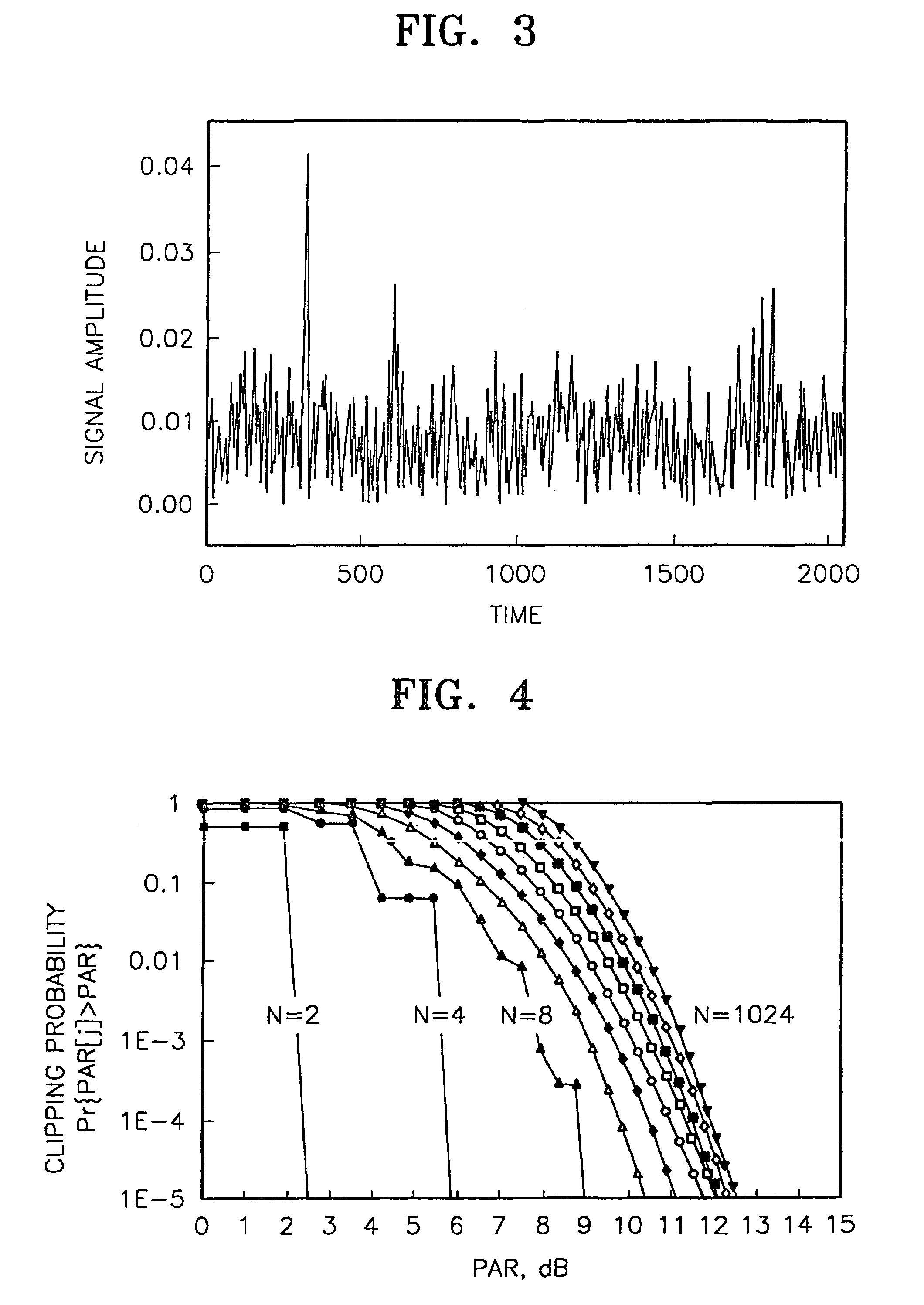
When the PAR is high, clipping or severe quantization noise may occur in the digital-to-analog converter of a transmission terminal.
When signals are transmitted, clipping and non-linear distortion may occur in a high power amplifier (HPA) of the R / F stage to thereby rapidly deteriorate performance.
If a HPA is restricted to operate at a low power intentionally to avoid this problem, the efficiency of the HPA and total system performance can be deteriorated.
The conventional algorithm for reducing the PAR of the OFDM signal is simple and very effective when the size N of the OFDM symbol is small, however, inappropriate for when N is large.
In the algorithm adopted when N is large, as the PAR decreases much, the complexity and the information loss are increased.
But, the above methods cannot be adopted for an OFDM symbol for which N is greater than 16.
However, this method is disadvantageous in that as peak power is reduced, more-information is lost.
1–5, 1997, by Stefan H. Muller and Johannes B. Huber. By these methods, a hardware configuration becomes complicated because various N-point IFFTs should be simultaneously performed.
Information loss can be generated because phase change information must be transmitted together with data.
In the conventional single carrier transmission method, PAR is not great and thus the above-described problems of the OFDM system are not generated.
When the data transmission rate is increased, signal interference by a channel is rapidly increased, so that the number of equalizer taps of the receiving unit must be increased.
At this time, the training of the equalizer requires much time and the operation thereof is complicated.
But, the PAR of the OFDM signal is great so that it is difficult for the OFDM method to be utilized.
In particular, under a channel environment having severe fading, a channel changes more rapidly, so much transmission information cannot be decoded if the channel is not properly estimated.
The method of estimating a channel using a reference symbol is appropriate for an environment having little change in the characteristics of the channel, but causes many channel estimation errors in a channel environment having severe fading.
However, when the channel change becomes severe, much fluctuation occurs between pilot tones added at regular intervals in the frequency domain in the transmitting stage, thus making a channel estimation error worse.
However, these references do not consider the PAR at all, so that many problems are generated in actual system implementation.

Method used


Image

  • Method for transmitting and receiving orthogonal frequency division multiplexing signal and apparatus therefor
  • Method for transmitting and receiving orthogonal frequency division multiplexing signal and apparatus therefor
  • Method for transmitting and receiving orthogonal frequency division multiplexing signal and apparatus therefor

Examples


Embodiment Construction

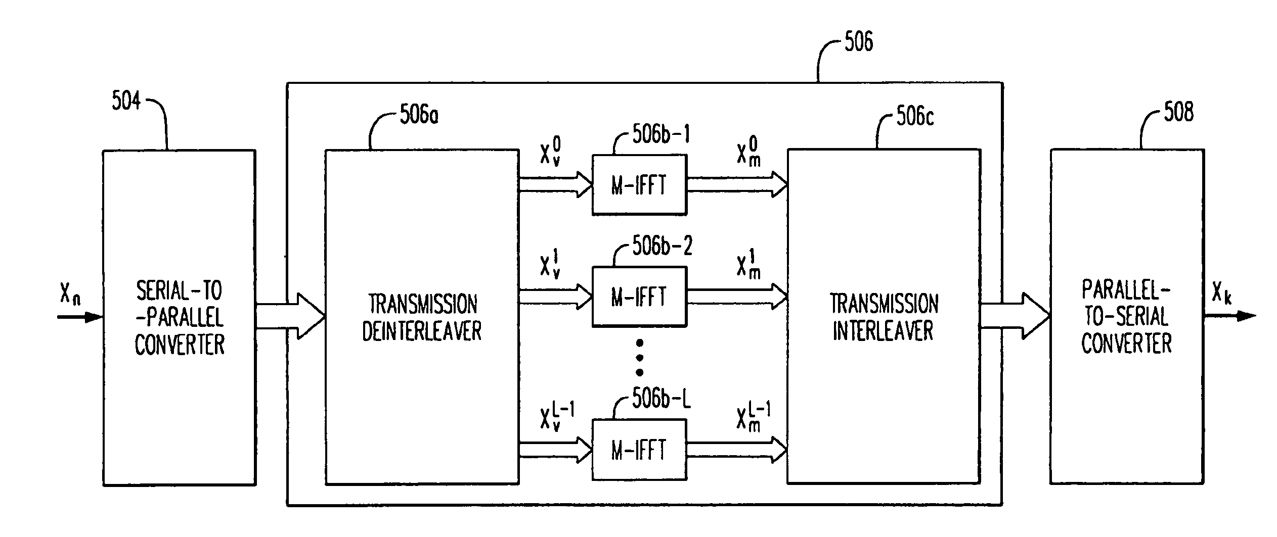
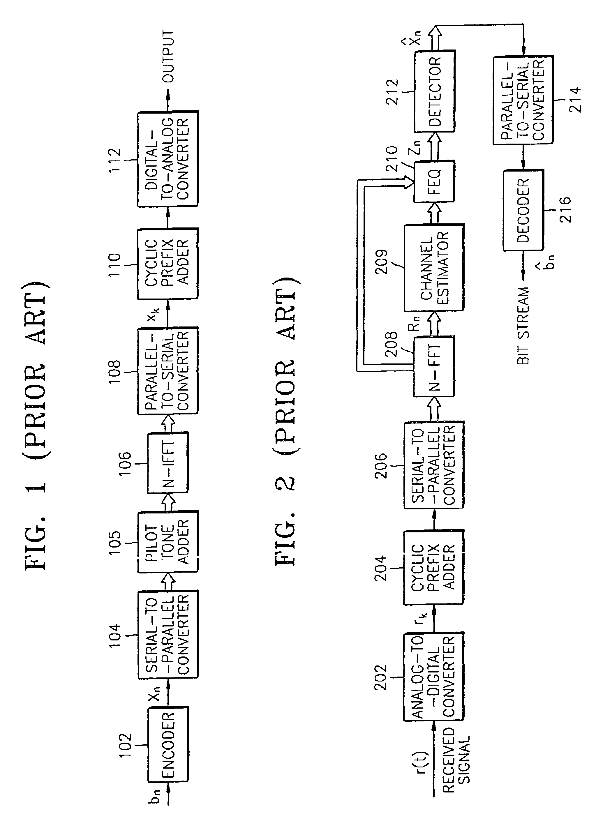
[0071]Referring to FIG. 5, a signal transmitting apparatus according to an embodiment of the present invention includes an encoder 502, a serial-to-parallel converter 504, an L-distribution M-point inverse fast Fourier transformer (L*(M-IFFT)) 506, a parallel-to-serial converter 508, a cyclic prefix adder 510 and a digital-to-analog converter 512. The structure of the signal transmitting apparatus of FIG. 5 is similar to that of the conventional signal transmitting apparatus of FIG. 1. That is, the L*(M-IFFT) 506 instead of the N-IFFT 106 of the conventional signal transmitter is used, and the encoder 502, the serial-to-parallel converter 504, the parallel-to-serial converter 508, the cyclic prefix adder 510 and the digital-to-analog converter 512 according to the present invention correspond to the encoder 102, the serial-to-parallel converter 104, the parallel-to-serial converter 108, the cyclic prefix adder 110 and the digital-to-analog converter 112, respectively.

[0072]FIG. 6 sh...


PUM


Abstract

A method for transmitting orthogonal frequency division multiplexing (OFDM) signals including coding the OFDM signals; forming a block of N coded data and dividing the block into L M-sized small blocks; M-point inverse fast Fourier transforming the L small blocks; combining the transformed blocks to generate an N-sized inversely-transformed block; attaching a cyclic prefix to the N-sized block; and transforming the blocks into an analog signal; and transmitting the analog signal. A method of receiving OFDM signals including digitally converting received OFDM signals and obtaining a samples from the transformed signals; detecting the starting point of an N-sized signal sample block from the samples; dividing the signal sample block into L M-sized small blocks M-point fast Fourier transforming the L small blocks; combining the transformed small blocks to generate an N-sized transform block; detecting data from the generated block, and decoding the detected data. N, M and L are integers of 1 or more and L=N / M.

Description

BACKGROUND OF THE INVENTION[0001]1. Field of the Invention[0002]The present invention relates to a signal transmitting method and apparatus, and more particularly, to a signal transmitting method and apparatus by which an orthogonal frequency division multiplexing (OFDM) method is improved.[0003]2. Description of the Related Art[0004]As a transmission rate is increased when data is transmitted through a wire or wireless channel, multipath fading or intersymbol interference (ISI) is increased, so that reliable data transmission cannot be expected. Orthogonal frequency division multiplexing (OFDM) and discrete multitone (DMT) are resistant to the multipath fading and ISI and their band efficiencies are high, so that they are adopted in the signal transmitting method of a digital audio broadcast (DAB) and digital television (TV) in Europe, and they are used for an asymmetric digital subscriber line (ADSL) and a universal asymmetric digital subscriber line (UADSL) in U.S.A.[0005]FIG. 1 ...

Claims


Application Information

Patent Timeline
IPC IPC(8): H04L27/26H04L1/00H04J11/00H04L25/03H04N5/44H04N19/00H04N19/436H04N19/46H04N19/60H04N19/70H04N19/80
CPCH04L1/0071H04L27/2614H04L27/2628H04L27/2633H04L25/03012H04L27/26522
Inventor KIM, YUNG-SOOPARK, JI-HOON
Owner SAMSUNG ELECTRONICS CO LTD
Learn More