Cycle handlebar shock and vibration damper

a technology for bicycle handlebars and handlebars, which is applied in the direction of friction roller transmission, steering devices, cycle equipments, etc., can solve the problems of direct transfer of shock and vibration in the frame structure, and achieve the effects of reducing shock and vibration, reducing sharp shock waves and constant pulsation

Inactive Publication Date: 2005-10-11
VANDEMORTEL DENNIS R
View PDF5 Cites 41 Cited by
  • Summary
  • Abstract
  • Description
  • Claims
  • Application Information

AI Technical Summary

Benefits of technology

[0014]Therefore, the primary object of the invention is to decrease the shock and vibration that is transferred through the handlebars to a rider on a motorcycle or bicycle. The reduction is accomplished by isolating the handlebars from the triple clamp, and utilizing a resilient damping material in between the two upright cradles which does not completely eliminate all transferred shock and vibration but reduces it significantly.
[0015]An important object of the invention is that the reduction in the sharp shock waves and constant pulsation helps considerably in preventing wrist injury, which is prevalent for riders of motorcycles or bicycles, especially those traveling rapidly over rugged terrain such as motocross or mountain biking.
[0016]Another object of the invention is the decrease of rider fatigue which can be a very important advantage over the conventional approach. In time, the vibration on the handlebars transferred through to the rider's arms requir

Problems solved by technology

The difficulty with this conventional design is the fact that the handlebar is rigidly attached to the clamp, ther

Method used


Image

  • Cycle handlebar shock and vibration damper
  • Cycle handlebar shock and vibration damper
  • Cycle handlebar shock and vibration damper

Examples


Embodiment Construction

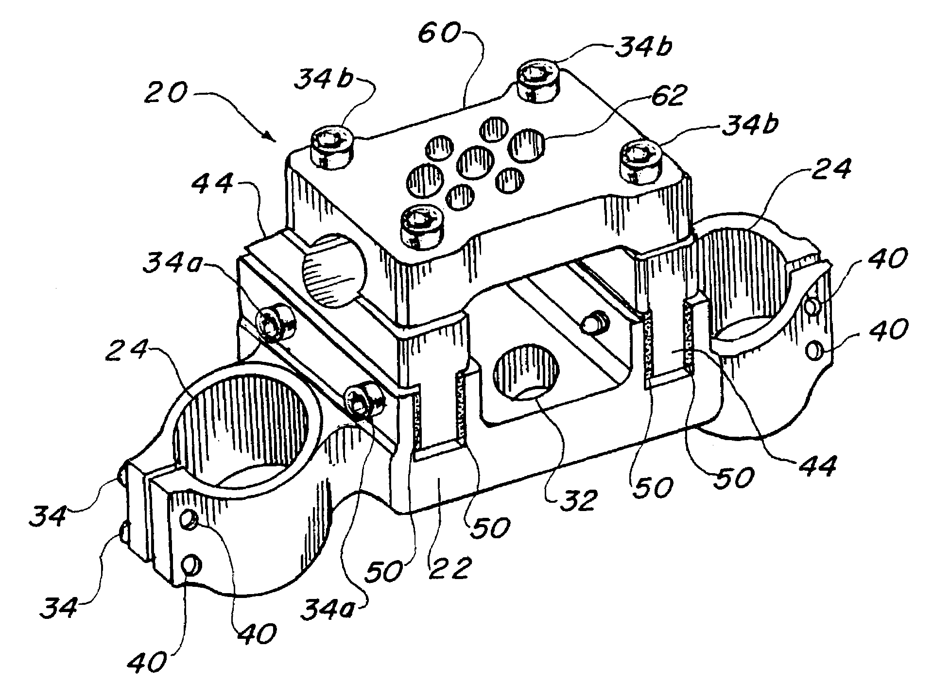
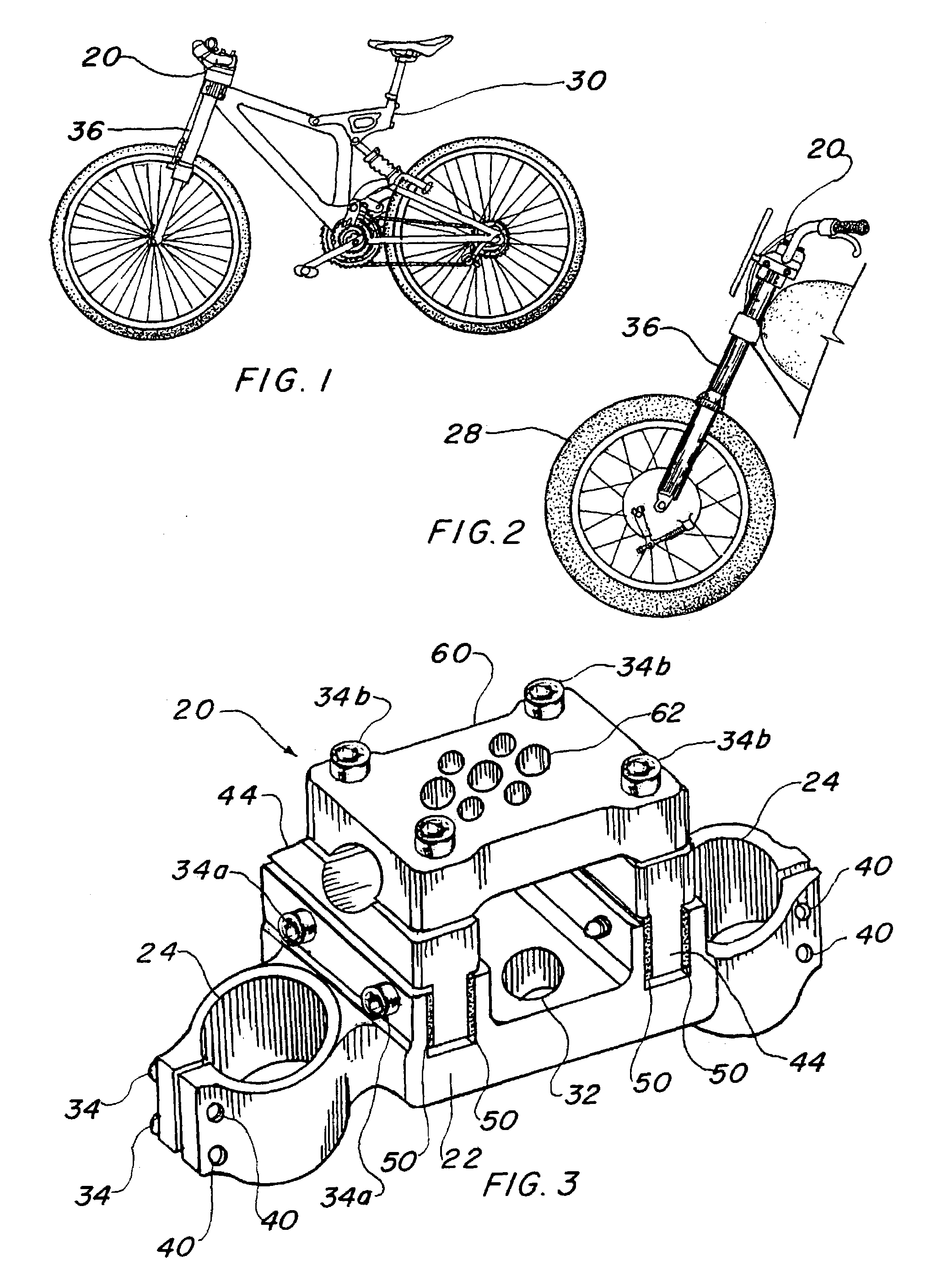
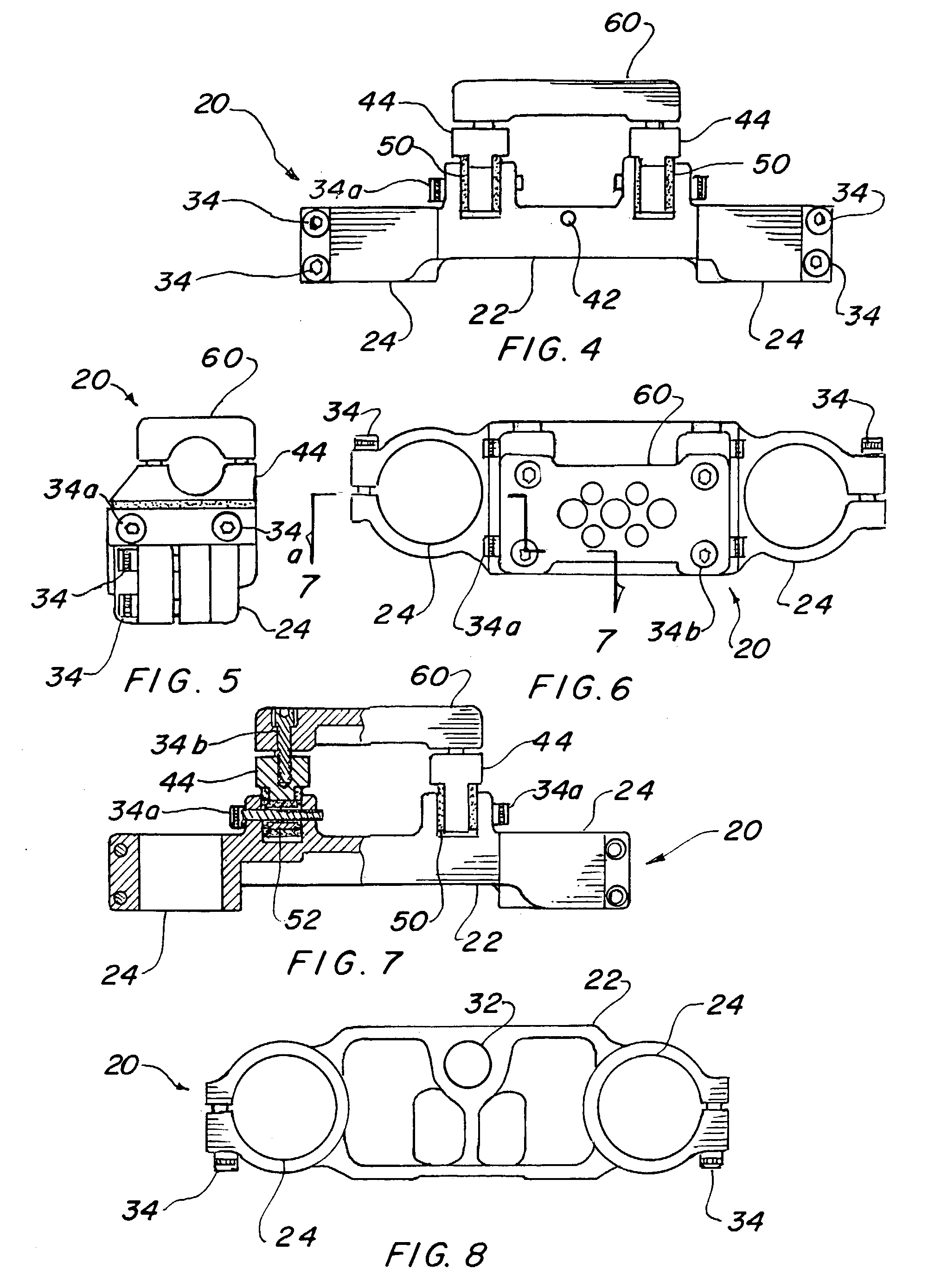
[0050]The best mode for carrying out the invention is presented in terms of a preferred embodiment for a shock and vibration reducing triple clamp which may be used on a motorcycle or a bicycle. The preferred embodiment of the shock and vibration reducing triple clamp 20, as shown in FIGS. 1 through 29, is comprised of a handlebar triple clamp body 22 that includes a pair of integral front fork mounting rings 24 positioned on opposed distal ends of the body 22. The body 22 also has a pair of integral upright cradles 26, with each located adjacent to one of the fork mounting rings 24. FIGS. 3–8 illustrate the shock and vibration reducing triple clamp 20 in its assembled condition including all of the hardware necessary to attach a handlebar and shock absorbing forks to a motorcycle 28 or bicycle 30. FIGS. 1 and 2 illustrate the invention mounted on each respective vehicle 28 and 30, as no other modification or accessories are necessary.

[0051]In order to install the invention to a mot...


PUM


Abstract

A handlebar shock and vibration damper triple clamp (20) for a motorcycle or a bicycle is taught which comprises a handlebar triple clamp body (22) with a pair of clamps that holds the handlebar in isolation from the body. The body has a pair of integral front fork mounting rings (24) positioned on opposite ends, and a pair of upright cradles (26) adjacent to the rings. A lower handlebar clamp (44) is positioned within each cradle such that the clamp is completely segregated from the triple clamp body. Resilient isolation strips (50) and cylinders (52) engage the upright cradles and lower handlebar clamps, thereby providing a pliant interface therebetween. An upper handlebar bridge clamp (60) is disposed above each lower handlebar clamp such that a handlebar may be inserted and compressably retained therebetween, thus decreasing vibration and shock impulses upon the handlebar during operation of the cycle due to the elastic nature of the interface.

Description

TECHNICAL FIELD[0001]The invention generally relates to handlebar clamping brackets for two-wheeled cycles and more specifically, to a handlebar clamping bracket for a motorcycle or bicycle that provides shock and vibration dampening.BACKGROUND ART[0002]Previously, many types of handlebar mounting brackets have been used to provide an effective means of holding the handlebar on a motorcycle or bicycle. In most cases the handlebar is clamped between two elements which allows angular positioning and ease of removal for replacement. While prior art has developed a myriad of dampening devices for the front forks of motorcycles and bicycles, little has been done to isolate the handlebars for shock and vibration.[0003]The prior art listed below did not disclose any patents that possess the novelty of the instant invention, however the following U.S. patents are considered related:[0004]U.S. Pat. No.InventorIssue Date3,989,261KawaguchiNov. 2, 19764,515,384Honma, et al.May 7, 19854,807,860S...

Claims


Application Information

Patent Timeline
IPC IPC(8): B62K21/20B62K21/00B62K21/14
CPCB62K21/14Y10T74/20786
Inventor VANDEMORTEL, DENNIS R.
Owner VANDEMORTEL DENNIS R
Why Eureka
Try Eureka