Electro-optical panel, electro-optical device, and electronic apparatus

a technology of electrooptical devices and electronic devices, applied in the direction of identification means, devices with multiple display units, instruments, etc., can solve the problems of increasing power consumption, and achieve the effects of reducing cost, reducing power consumption, and reducing the number of components

Active Publication Date: 2005-10-11
BOE TECH GRP CO LTD
View PDF11 Cites 60 Cited by
  • Summary
  • Abstract
  • Description
  • Claims
  • Application Information

AI Technical Summary

Benefits of technology

[0015]According to the electro-optical panel, at least part of a drive signal supplied to the first panel can be supplied to the second panel. In other words, the common drive signal can be supplied from the single drive circuit to the first panel and the second panel. It is thus unnecessary to provide separate drive circuits for driving the first panel and the second panel. As a result, the power consumption can be greatly reduced, the number of components can be reduced, and the cost can be reduced.
[0016]In the foregoing arrangement, the drive circuit may be mounted on the first panel. Accordingly, the drive circuit can be fixed at a given position. Also, the space occupied by the electro-optical panel including the drive circuit can be reduced.
[0022]In the electro-optical panel arranged as described above, the first electrode and the third electrode may be substantially linear, and the first electrode and the third electrode may be disposed substantially parallel to each other. Accordingly, the first electrode and the third electrode can be connected to each other by substantially the shortest distance. Thus, the drive signal to be supplied to both electrodes is prevented from being delayed.
[0025]In the electro-optical panel arranged as described above, the drive circuit may include the functions of stopping a signal supply to the fourth electrode when the first panel is displaying; and stopping a signal supply to the second electrode when the second panel is displaying. Accordingly, the unused panel can be non-displaying, and the power consumption can be reduced.
[0028]An electronic apparatus according to the present invention includes the electro-optical device arranged as described above. According to the electronic apparatus, a multiple-display can be achieved using the first panel and the second panel. The power consumed by the electro-optical device portion can be suppressed, and hence the power consumed by the electronic apparatus can also be reduced.

Problems solved by technology

When the main display and the sub-display are driven by separate drive circuits, as described above, there is a problem that the power consumption increases.

Method used


Image

  • Electro-optical panel, electro-optical device, and electronic apparatus
  • Electro-optical panel, electro-optical device, and electronic apparatus
  • Electro-optical panel, electro-optical device, and electronic apparatus

Examples


Embodiment Construction

[0049]Electronic Apparatus

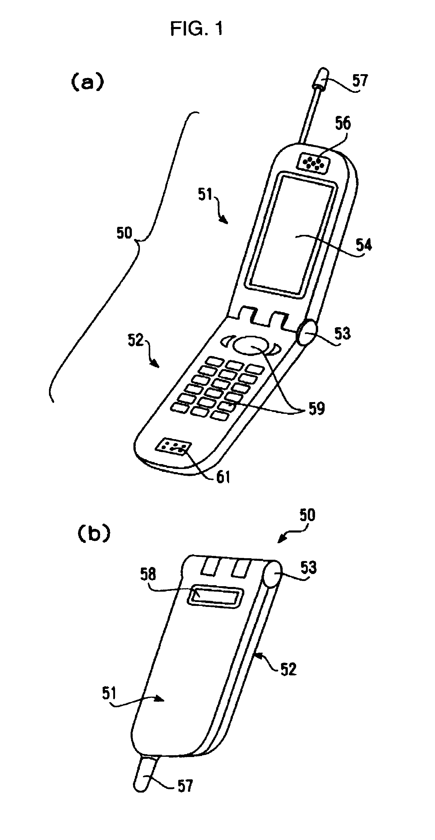
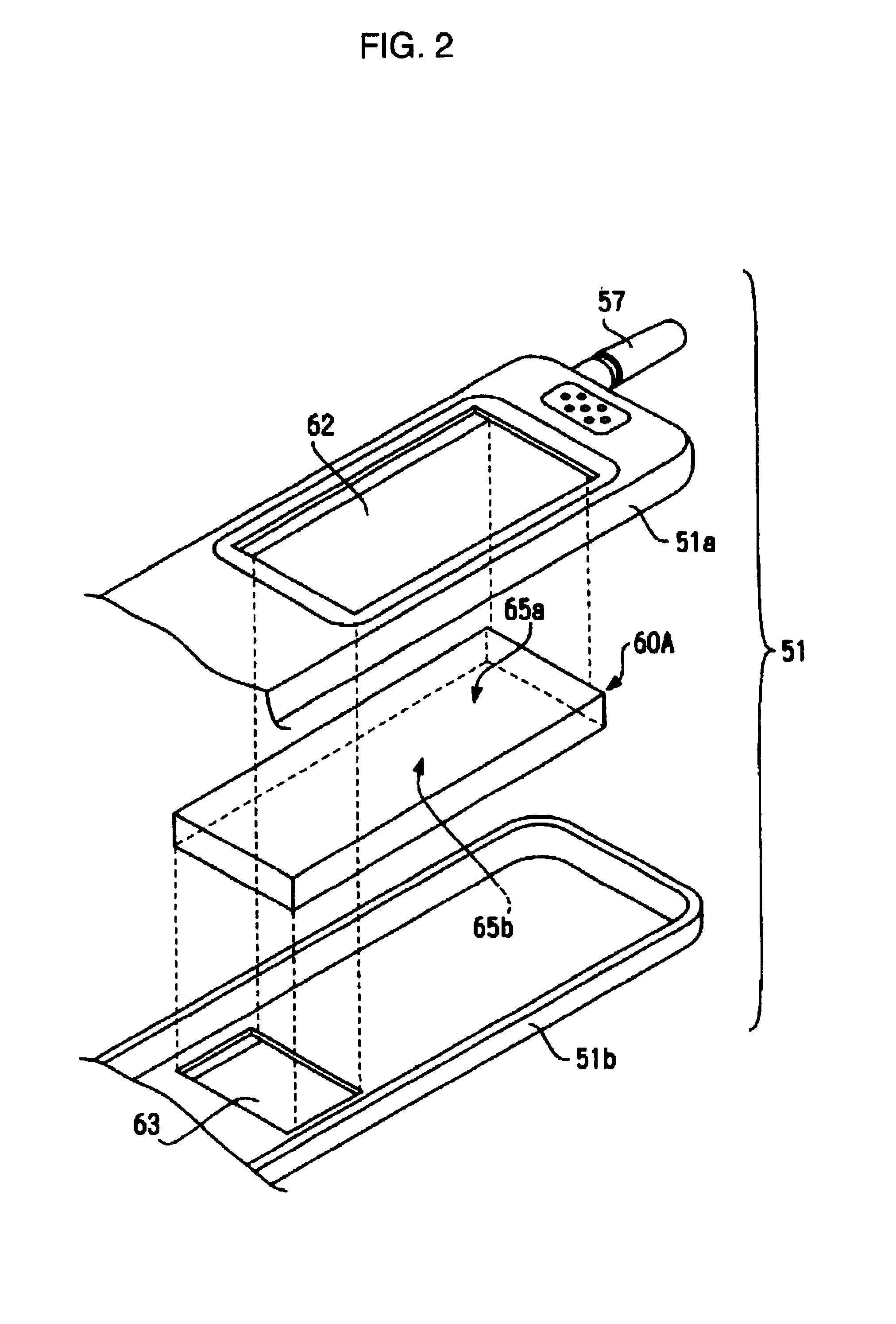
[0050]Hereinafter an embodiment of an electronic apparatus according to the present invention will be described using a flip cellular phone as an example. FIG. 1 includes perspective views of the cellular phone. Specifically, FIG. 1(a) illustrates the unfolded cellular phone, and FIG. 1(b) illustrates the folded cellular phone. FIG. 2 is an exploded perspective view of part of a first body including a display of the cellular phone.

[0051]A cellular phone 50 includes a first body 51 and a second body 52. These bodies 51 and 52 are movably connected to each other by a hinge 53. The first body 51 includes an earpiece 56 and an antenna 57. The second body 52 includes a plurality of operation keys 59 and a mouthpiece 61. As shown in FIG. 1(a), a main display 54 is provided on the inner surface of the first body 51. As shown in FIG. 1(b), a sub-display 58 is provided on the outer surface of the first body 51.

[0052]The angle between the two bodies 51 and 52 around ...


PUM

PropertyMeasurementUnit
flexibleaaaaaaaaaa
widthaaaaaaaaaa
electricallyaaaaaaaaaa

Abstract

A liquid crystal device 60A includes a main display 1A and a sub-display 2A. Signals are supplied from a drive circuit 7 to first electrodes 15a and second electrodes 15b included in the main display 1A and third electrodes 15c and fourth electrodes 15d included in the sub-display 2A. Some of the first electrodes 15a of the main display 1A are electrically connected to the third electrodes 15c of the sub-display 2A.

Description

BACKGROUND OF THE INVENTION[0001]1. Technical Field of the Invention[0002]The present invention relates to an electro-optical panel which has a panel structure containing an electro-optical material, to an electro-optical device which has a structure including an electro-optical material, and to an electronic apparatus formed by using the electro-optical device.[0003]2. Description of the Related Art[0004]An electro-optical panel is a panel structure that can be made available on the market as a single unit. By mounting a wiring board such as an FPC (Flexible Printed Circuit) to the electro-optical panel, signals and a power supply voltage can be supplied from an external circuit to the electro-optical panel through the wiring board. By attaching an illuminator to the electro-optical panel, light can be supplied to the electro-optical panel.[0005]In general, electro-optical panels are regarded as electro-optical components which have no accessory devices such as wiring boards and il...

Claims


Application Information

Patent Timeline
Patent Type & Authority Patents(United States)
IPC IPC(8): G02F1/13H04M1/02G02F1/133G02F1/1347G09F9/00G09F9/40G09G3/20G09G3/36
CPCG02F1/13452H04M1/0214H04M2250/16
Inventor KURASHIMA, TAKESHIENDO, KOGOSATO, AKIRAUSHIKI, TAKEYOSHI
Owner BOE TECH GRP CO LTD
Why Eureka
Try Eureka