Simplified defibrillator output circuit

a defibrillator and output circuit technology, applied in the field of electronic circuitry, can solve the problems of no practical use, no defibrillator used, and system use is far more complicated

Inactive Publication Date: 2005-10-11
CAMERON HEALTH
View PDF64 Cites 119 Cited by
  • Summary
  • Abstract
  • Description
  • Claims
  • Application Information

AI Technical Summary

Problems solved by technology

This system is far more complicated to use than current ICD systems using transvenous lead systems together with an active can electrode and therefore it has no practical use.
It has in fact never been used because of the surgical difficulty of applying such a device (3 incisions), the impractical abdominal location of the generator and the electrically poor sensing and defibrillation aspects of such a system.
ICDs are very effective at treating V-Fib, but are therapies that still require significant surgery.
In addition, chronic transvenous lead systems, their reimplantation and removals, can damage major cardiovascular venous systems and the tricuspid valve, as well as result in life threatening perforations of the great vessels and heart.
Consequently, use of transvenous lead systems, despite their many advantages, are not without their chronic patient management limitations in those with life expectancies of >5 years.
The problem of lead complications is even greater in children where body growth can substantially alter transvenous lead function and lead to additional cardiovascular problems and revisions.
Moreover, transvenous ICD systems also increase cost and require specialized interventional rooms and equipment as well as special skill for insertion.
However, an AED must be used by another individual, not the person suffering from the potential fatal rhythm.
Because >75% of cardiac arrests occur in the home, and over half occur in the bedroom, patients at risk of cardiac arrest are often alone or asleep and can not be helped in time with an AED.
Circuitry for controlling so-called “high side” switches in defibrillator circuitry has exhibited considerable complexity, necessitating use, for example, of transformers, opto-couplers and / or photo voltaic generators.
Such complexity is generally undesirable and particularly undesirable in devices intended for implantation within the human body.

Method used


Image

  • Simplified defibrillator output circuit
  • Simplified defibrillator output circuit
  • Simplified defibrillator output circuit

Examples


Embodiment Construction

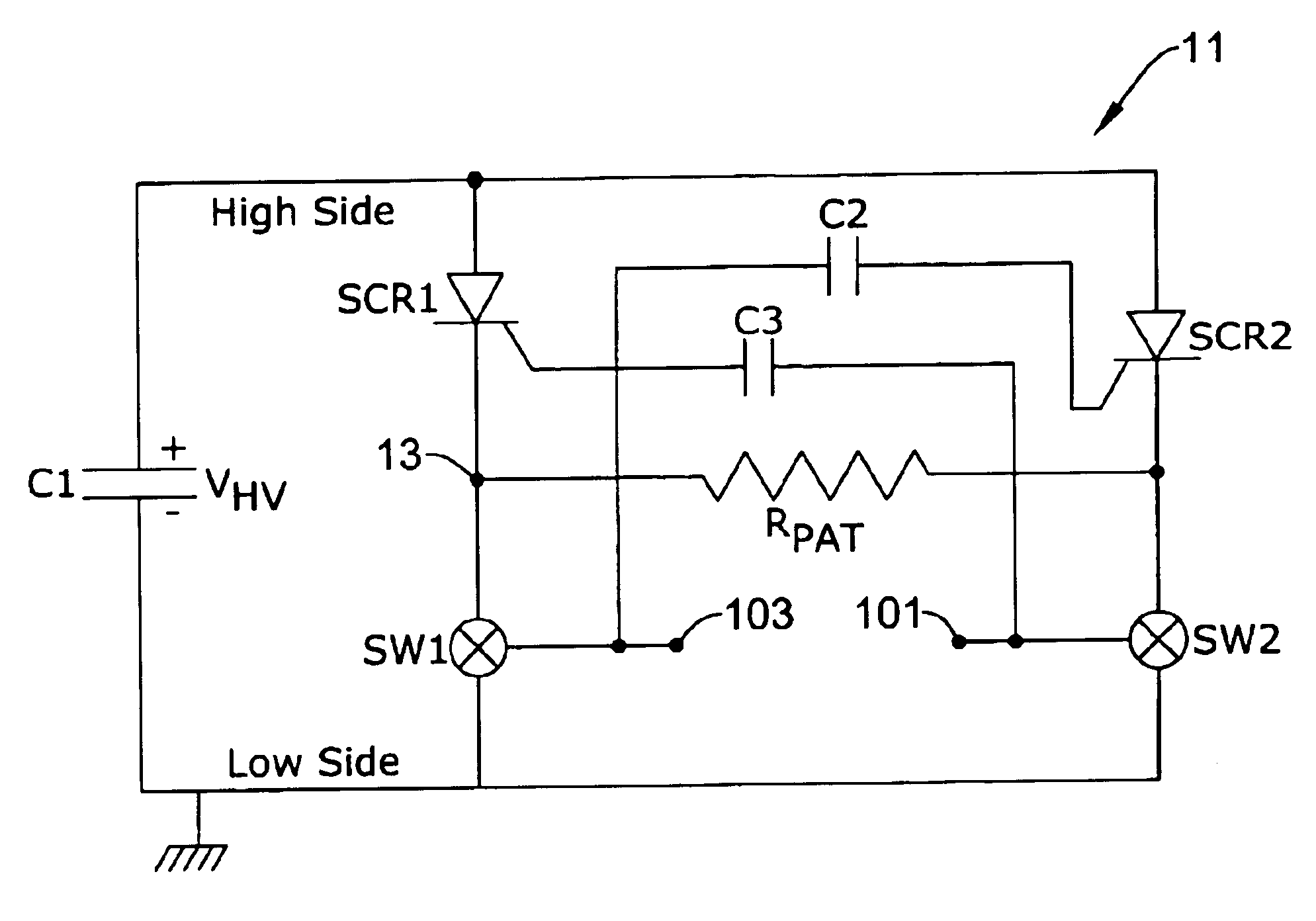
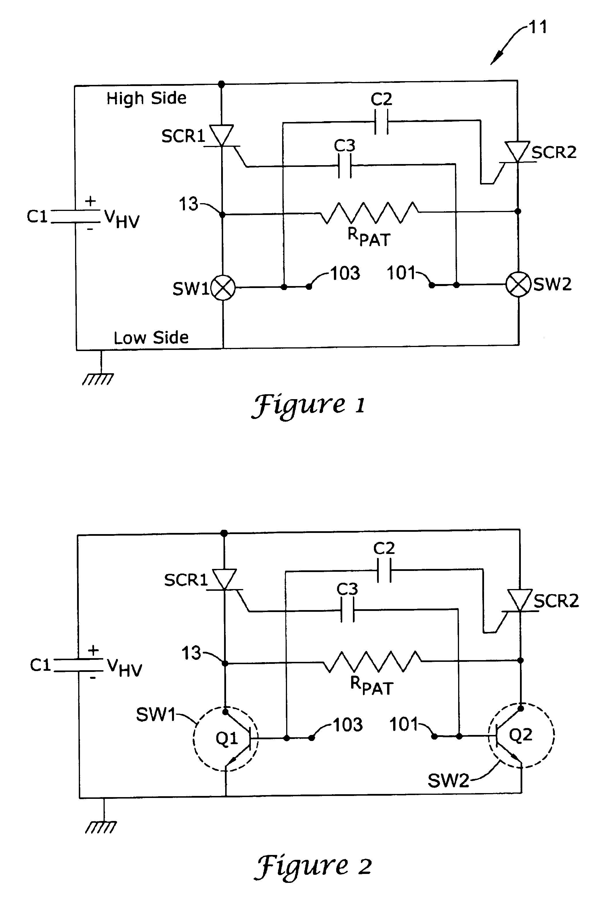
[0019]FIG. 1 illustrates an electrical circuit including a first illustrative embodiment according to the invention. The circuit includes a high voltage capacitor C1 grounded at one terminal and connected at its opposite terminal to respective anodes of two silicon controlled rectifiers SCR1, SCR2.

[0020]The respective cathodes of the respective rectifiers SCR1, SCR2 are connected to respective first terminals of first and second low side switches SW1, SW2. The respective cathodes of the silicon controlled rectifiers SCR1, SCR2 are additionally electrically coupled to respective physical locations on a patient on either side of a patient resistance denoted RPAT.

[0021]The gate or trigger terminal of the first silicon controlled rectifier SCR1 is connected through a capacitor C3 to a first terminal 101 of the second switch SW2. The gate or trigger terminal of the second silicon controlled rectifier SCR2 is connected through a second capacitor C2 to the first terminal 103 of the first l...


PUM


Abstract

High side driver circuitry for a defibrillator circuit employs respective capacitors connected to respective gates of silicon controlled rectifiers serving as high side switches. Applying a voltage pulse to a selected capacitor turns on the associated SCR. Positive turn-on of the high side SCRs is insured by inserting a constant current source into the low side activation current path at start-up.

Description

RELATED APPLICATIONS[0001]The invention of present application may find use in systems such as are disclosed in the U.S. patent application entitled “SUBCUTANEOUS ONLY IMPLANTABLE CARDIOVERTER-DEFIBRILLATOR AND OPTIONAL PACER,” having Ser. No. 09 / 663,607, filed Sep. 18, 2000, pending, and U.S. patent application entitled “UNITARY SUBCUTANEOUS ONLY IMPLANTABLE CARDIOVERTER-DEFIBRILLATOR AND OPTIONAL PACER,” having Ser. No. 09 / 663,606, filed Sep. 18, 2000, pending, of which both applications are assigned to the assignee of the present application, and the disclosures of both applications are hereby incorporated by reference.[0002]Applications related to the foregoing applications include a U.S. patent application Ser. No. 09 / 940,283 entitled “DUCKBILL-SHAPED IMPLANTABLE CARDIOVERTER-DEFIBRILLATOR CANISTER AND METHOD OF USE,” U.S. patent application Ser. No. 09 / 940,371 entitled “CERAMICS AND / OR OTHER MATERIAL INSULATED SHELL FOR ACTIVE AND NON-ACTIVE S-ICD CAN,” U.S. patent application...

Claims


Application Information

Patent Timeline
Patent Type & Authority Patents(United States)
IPC IPC(8): A61N1/39
CPCA61N1/39A61N1/3912A61N1/3956
Inventor OSTROFF, ALAN H.
Owner CAMERON HEALTH
Why Eureka
Try Eureka