Reinforced pallet

a technology of reinforced pallets and reinforcements, applied in packaging, manufacturing tools, transportation and packaging, etc., can solve the problems of insufficient reinforcement for racking loads and line loads, inconvenient size adjustment, and inability to meet the needs of racking loads,

Inactive Publication Date: 2005-10-18
REHRIG PACIFIC CO INC
View PDF72 Cites 41 Cited by
  • Summary
  • Abstract
  • Description
  • Claims
  • Application Information

AI Technical Summary

Benefits of technology

[0011]It is an object according to the present invention to provide a plastic

Problems solved by technology

While reinforced plastic pallets presently exist, most do not provide sufficient reinforcement for racking loads and line loads.
For example, a non-continuous, multiple piece cross-reinforcement may do little to support racking loads.
Some reinforced pallets today may attempt to handle various load types, such as line loads and racking loads, but are ultimately not size efficient or cost efficient.
In other words, these pallets may not provide the end user with the desired strength and load bearing properties for the desired pallet package height.
Moreover, many reinforced pallets have reinforcement which is exposed.
This is a particularly undesirable feature in the case where the reinforcement is made from fiberglass or other fiber materi

Method used


Image

  • Reinforced pallet
  • Reinforced pallet
  • Reinforced pallet

Examples


second embodiment

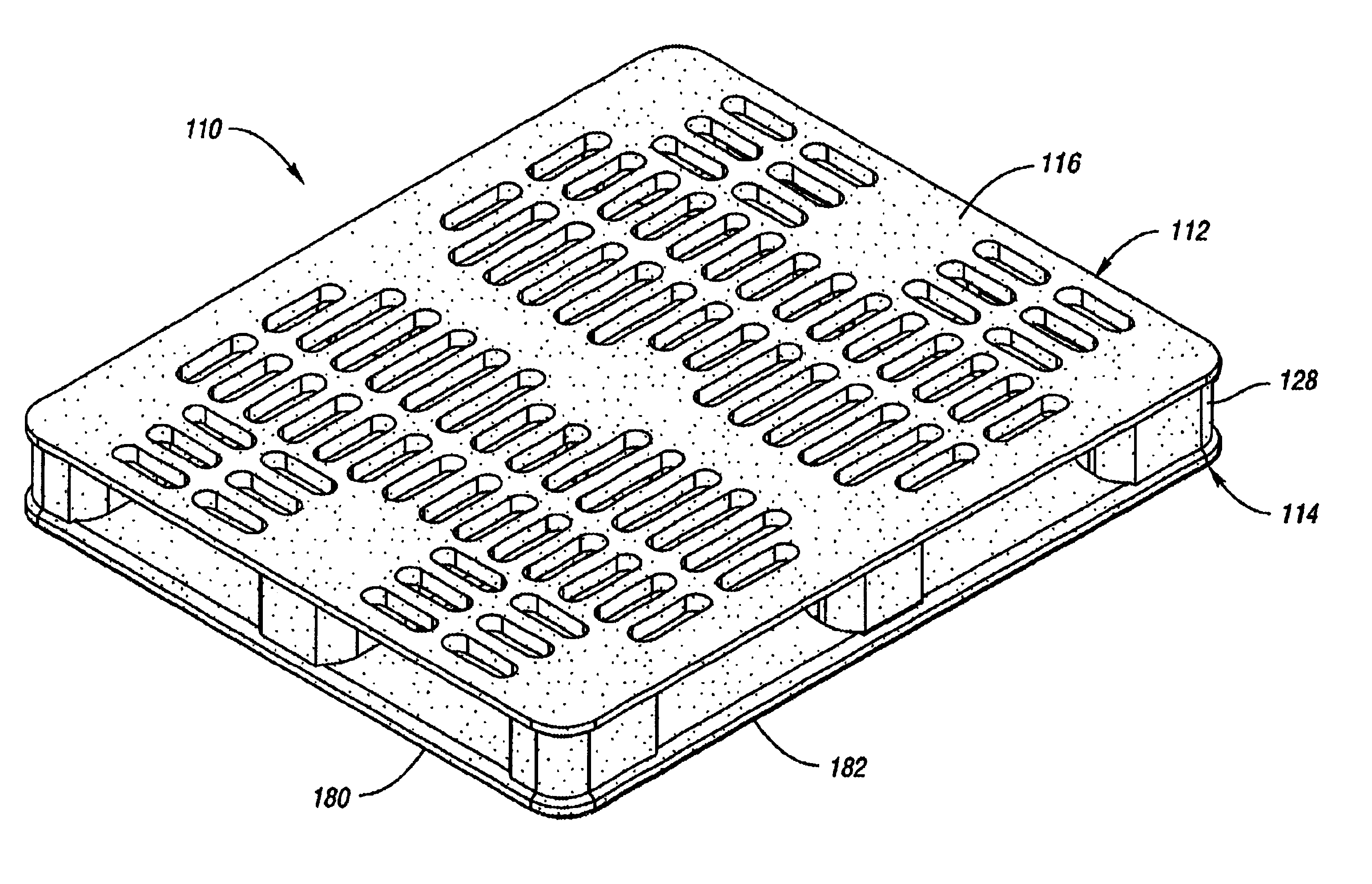
[0089]FIGS. 12-22 illustrate a pallet 110 according to a second embodiment of the present invention. Components similar to those of the first embodiment have a corresponding reference number with a “1” prefix. Pallet 110 is similar to pallet 10, but has a bottom deck 114 with a single cross-rail 188 having therein a first continuous cross-reinforcement member 150. Because the single cross-rail bottom deck design may have relatively lower bending and torsional strength compared to the first embodiment, additional top deck 112 reinforcement may be necessary. Accordingly, pallet 110 includes a pair of continuous cross-reinforcement members 160, 161 which lie in the transverse axis of top deck 112, as well as a pair of opposed peripheral reinforcement members 162, 164 proximate sides of top deck 112. Again, because pallet 110 includes one or more reinforcement members in top deck 112, the strength of pallet 110 is increased without increasing the thickness of the resulting pallet.

third embodiment

[0090]A third embodiment of according to the present invention is illustrated in FIGS. 23-33 as pallet 210, which includes top deck 212 and bottom deck 214. Components similar to those of the first embodiment have a corresponding reference number with a “2” prefix. Pallet 210 includes a plurality of peripheral reinforcement members 252, 254, 256, 258, and an integral formed cross-member 266 formed as unitary member with co-planar first and second cross-reinforcements 250 and 251. This unitary, continuous reinforcement 266 across bottom deck has sufficient strength characteristics such that no reinforcement may be necessary in top deck 212. While reinforcement could be added to top deck 212, this would increase the cost and weight of pallet 210.

[0091]In accordance with the teachings according to the present invention, such unitary cross-member 266 is preferable to a multi-piece, non-continuous, co-planar cross reinforcements within a single deck, and also to reinforcement members on ...

fourth embodiment

[0093]A fourth embodiment according to the present invention is shown in FIGS. 34-44 as pallet 310. Components similar to those of the first embodiment have a corresponding reference number with a “3” prefix. In this embodiment, note that bottom deck 314 includes an integrally formed, unitary reinforcement member 368, including cross-member portions 350, 351, as well as peripheral reinforcements 352, 354, 356, 358, which are generally continuous, and also generally has an inverted U-shaped cross-section. As with the third embodiment, the overall continuous nature of reinforcement member 368 within bottom deck 314 provides pallet 310 with the desired strength, as well as the desired line load and rack loading strength, and torsional strength. However, member 368 may be relatively more costly to manufacture.


PUM


Abstract

A reinforced pallet assembly having a first pallet deck and a second pallet deck. Each of the decks has an outer member and an intermediate member, each outer member and intermediate member having a one of a pair of mating cross-rib surfaces which are mounted together to define box-beam sections within each pallet deck. Also included is an elongate reinforcement member which is disposed between the outer member and the intermediate member of the second pallet deck for providing stiffness thereto. Further included is a plurality of columns which extend between the intermediate members.

Description

BACKGROUND OF THE INVENTION[0001]1. Field of the Invention[0002]The present invention relates to a reinforced pallet.[0003]2. Background Art[0004]Pallets are subject to many types of loads and forces. Many of these loads and forces are illustrated by pallet racking scenarios and line load scenarios. The line load is the weight of a unit load concentrated along a narrow area across the full length or width of the pallet. The rack load is the load carrying capacity and deflection of a pallet which is supported by a rack frame near the ends of the pallet stringers.[0005]Today, the use of plastic pallets is becoming more common. While reinforced plastic pallets presently exist, most do not provide sufficient reinforcement for racking loads and line loads. For example, a non-continuous, multiple piece cross-reinforcement may do little to support racking loads.[0006]Some reinforced pallets today may attempt to handle various load types, such as line loads and racking loads, but are ultima...

Claims


Application Information

Patent Timeline
IPC IPC(8): B65D19/00
CPCB65D19/0012B65D2519/00034B65D2519/00069B65D2519/00104B65D2519/00129B65D2519/00293B65D2519/00303B65D2519/00308B65D2519/00323B65D2519/00333B65D2519/00358B65D2519/00363B65D2519/00373B65D2519/00407B65D2519/00412B65D2519/00417B65D2519/00437B65D2519/00442B65D2519/00557B65D2519/00562B65D2519/00567B65D2519/00796Y10S108/902
Inventor APPS, WILLIAM P.
Owner REHRIG PACIFIC CO INC
Why Eureka
Try Eureka