Pipette washer

a technology of pipette washer and washer body, which is applied in the direction of cleaning using liquids, hollow article cleaning, laboratory glassware, etc., can solve the problems of difficult to achieve thoroughness, time-consuming and labor-intensive washing operation, and unwrappery of used pipette washers, etc., and achieves the effect of easy removal

Inactive Publication Date: 2005-10-18
SPEX CERTIPREP
View PDF24 Cites 31 Cited by
  • Summary
  • Abstract
  • Description
  • Claims
  • Application Information

AI Technical Summary

Benefits of technology

[0008]In accordance with the invention, a machine is provided to wash pipettes. Special internal structure is provided to achieve the thorough cleaning of pipettes. In addition, the structure also provides for the quick placement of pipettes into the inventive washer apparatus and for their easy removal. At the same time, convenience is provided by making it unnecessary to open and close the washer in order to clean pipettes. In addition, the structure of the inventive pipette washer provides for thorough cleaning of the inside and outside of the pipette.

Problems solved by technology

Likewise, even if a pipette is being used only for a single material, if it is to lie unused for a period of time, material remaining on the pipette may react, dry out, or otherwise change, thus making it undesirable to leave a used pipette unwashed.
It will be appreciated that pipettes must be washed both on the inside and the outside, although the challenge to obtain a well cleaned pipette is the thorough cleaning of the inside of the pipette.
Washing is complicated due to the narrow inner diameter of pipettes and the relatively inaccessible surfaces of bulbs on large volume pipettes.
Accordingly, it is important that washing be carried out easily and thoroughly, as delay will often only make the washing operation more time-consuming and difficult to achieve with thoroughness.

Method used


Image

  • Pipette washer
  • Pipette washer
  • Pipette washer

Examples


Embodiment Construction

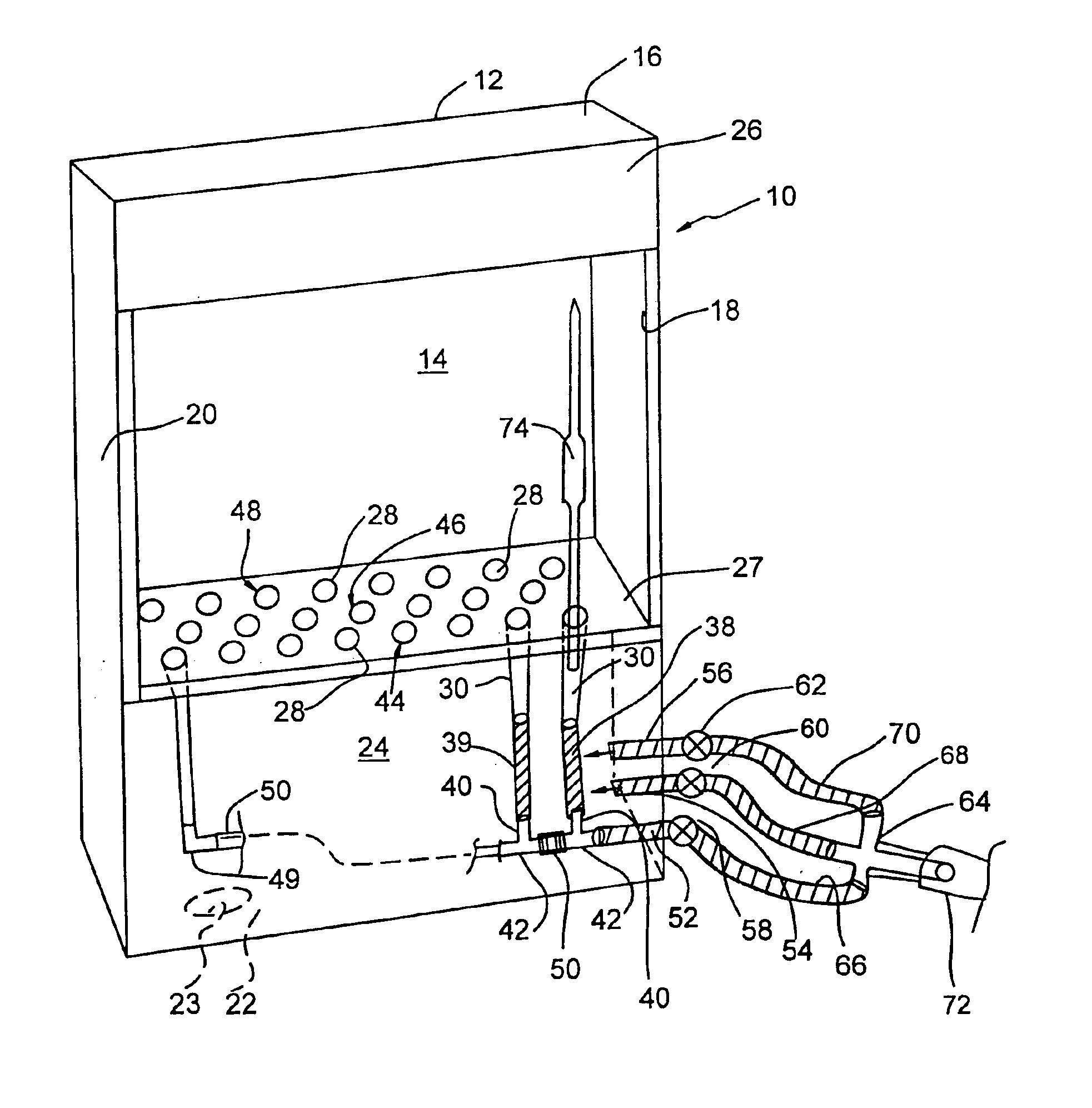
[0025]A pipette washer 10 constructed in accordance with the present invention is illustrated in perspective in FIG. 1. The pipette washer 10 comprises a housing 12. Housing 14 comprises a back panel 14, a top panel 16, and a pair of side panels 18 and 20. Housing 14 further comprises a bottom panel 22 defining a drain hole 23, a lower front panel 24, and an upper front panel 26.

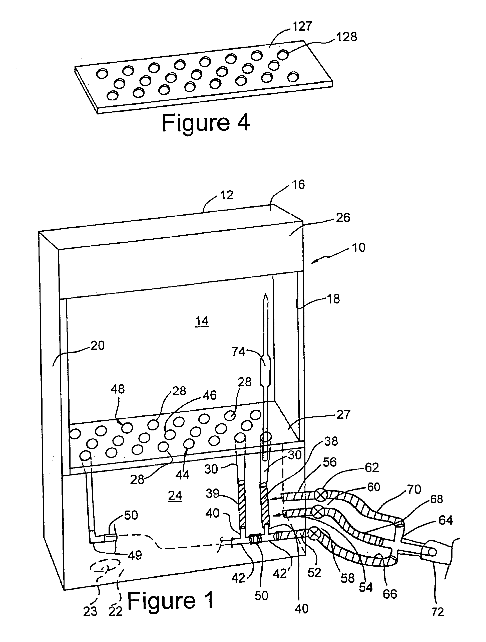
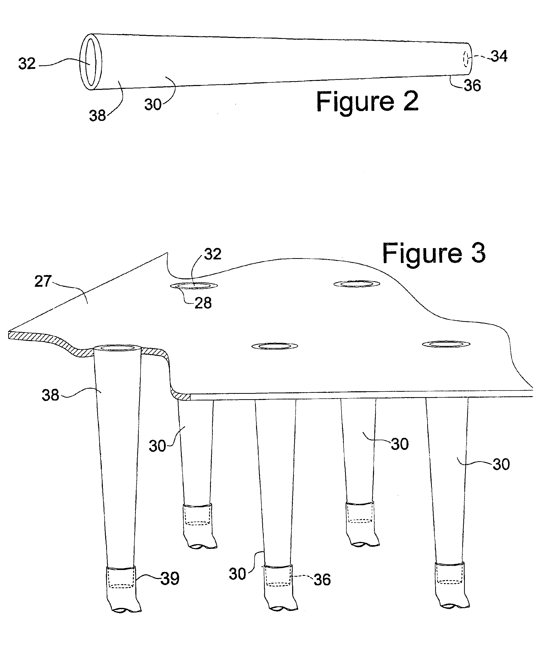
[0026]In accordance with the invention, a support rack 27 includes twenty-three circular holes 28. The various housing members are secured to each other and to support rack 27 using glue or other suitable means. Each circular hole 28 receives a pipette support cell 30, only two of which are illustrated in FIG. 1 for purposes of clarity of illustration. As illustrated in FIG. 2, support cells 30 have a generally tapered or conical shape and, for economical reasons may be made from plastic pipette tips which are available on the market from numerous suppliers. Each pipette support cell 30 has an upper opening ...


PUM


Abstract

A pipette washer comprising a plurality of cells for receiving pipettes is disclosed. Each of the cells comprises a top opening for receiving pipettes to be washed and a bottom opening. A support member supports the cells with the top opening accessible to receive pipettes to be washed. A hose system is coupled to the bottom opening on the cells. A supply hose is connected to the hose system. Each of the cells is supported in the support member with an orientation extending transverse to the horizontal. Each of the support cells comprises a cell member having a top width and a bottom width. The width is wider at the top and narrower at the bottom. In accordance with the preferred embodiment, each cell member is conical in shape. A housing contains and rechannels washing liquid while at the same time having an open front to allow for convenient access to the cells.

Description

TECHNICAL FIELD[0001]The present invention relates to the field of washing devices.BACKGROUND OF THE INVENTION[0002]Many measurement tasks involve the volumetric measurement of materials in liquid form. Such volumetric measurements may include measuring the amount of liquid taken from, for example, a lake, reservoir or other body of water which one wishes to test for environmental pollutants. In other applications, assembly line testing of samples may require reactants to be dispensed for use in a testing procedure. In similar fashion, manufacturing processes may require the input of measured amounts of reactants into a vessel in which a reaction, mixing, or other operation is being carried out.[0003]Typically, relatively small measured quantities of liquids are removed from a larger quantity of liquid using a pipette. Pipettes generally come in two forms. Some pipettes comprise elongated tubes which have a volume which is at least somewhat larger than the volume of liquid which the...

Claims


Application Information

Patent Timeline
Patent Type & Authority Patents(United States)
IPC IPC(8): B01L11/00B08B9/02B01L3/02B01L99/00
CPCB08B9/0323B01L99/00B01L3/021B01L2400/0487B01L13/02B01L3/0213
Inventor KOCHERLAKOTA, NIRMALAERNYEI, LASZLO
Owner SPEX CERTIPREP
Why Eureka
Try Eureka