Exhaust gas heat exchanger

Inactive Publication Date: 2005-10-18
SERCK HEAT TRANSFER +1
View PDF11 Cites 50 Cited by
  • Summary
  • Abstract
  • Description
  • Claims
  • Application Information

AI Technical Summary

Benefits of technology

[0004]It is an object of the present invention to provide an exhaust gas heat exchanger capable of functioning as a bypassable e

Problems solved by technology

Prior art exhaust gas coolers (such as that shown in FIGS. 1a-1c) are bulky and do not fit easily within the frequently cramped layout of the engine compartment of a road vehicle.
The p

Method used


Image

  • Exhaust gas heat exchanger
  • Exhaust gas heat exchanger
  • Exhaust gas heat exchanger

Examples


Embodiment Construction

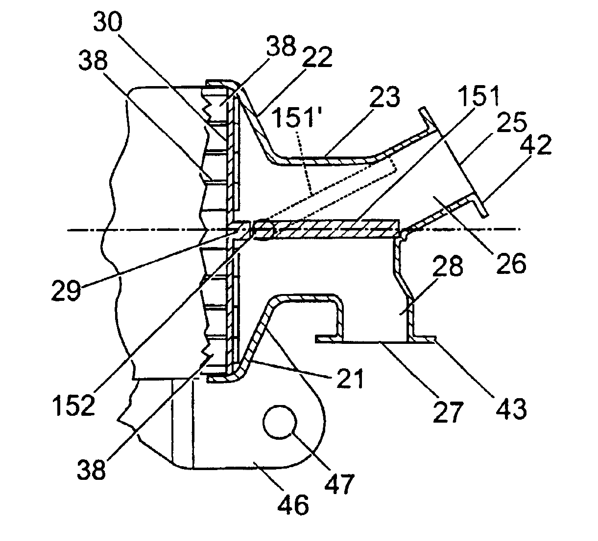
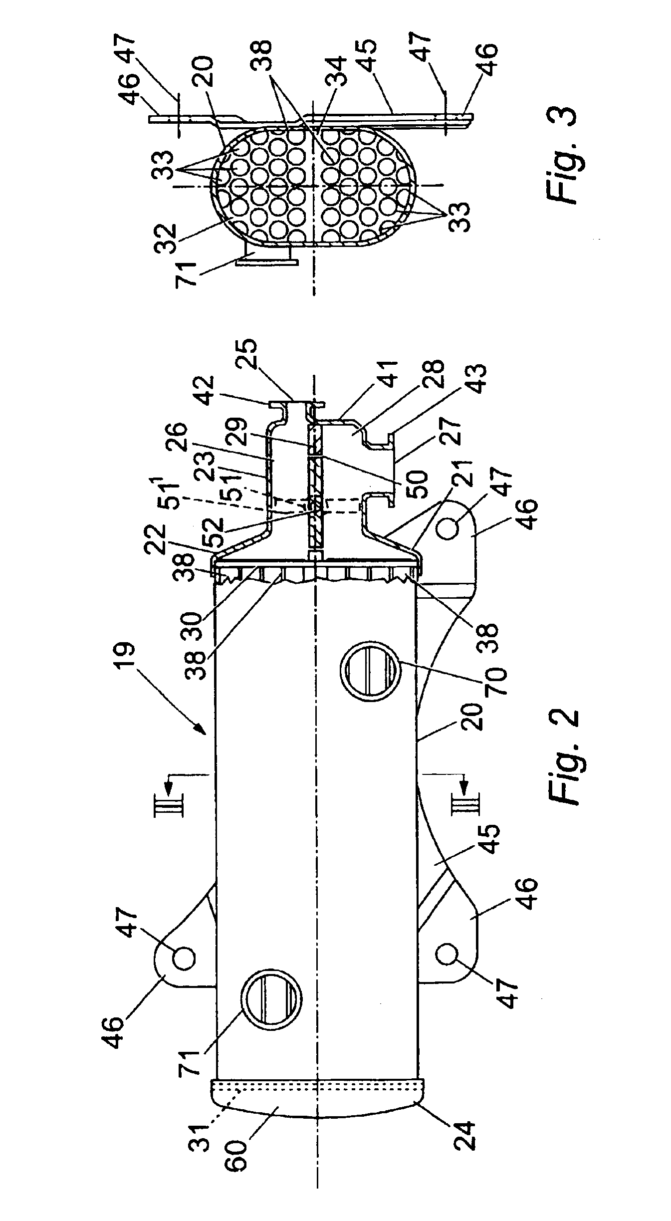
[0018]Referring first to FIGS. 2 to 5, these show an exhaust gas cooler 19 forming a first embodiment of exhaust gas heat exchanger in accordance with the invention. The cooler 19 comprises an external cylindrical shell 20. An exhaust gas manifold 21 is secured to one end of the shell 20, the manifold 21 being adapted to fit over the end of the shell 20 and be fastened thereto by any suitable means, e.g. by welding. The manifold 21 comprises a tapered conical portion 22 and a tubular portion 23 whose diameter is less than the diameter of the cylindrical shell 20. At the other end of the shell 20 is a domed cover portion 24 also adapted to fit over the end of the shell 20 and be secured thereto by suitable means, e.g. by welding. The volume between this end of the shell 20 and the domed cover 24 constitutes a further exhaust gas chamber 60 whose purpose will be subsequently detailed.

[0019]The tubular portion 23 is provided with an exhaust gas inlet 25 which opens in to a first exhaus...


PUM


Abstract

An exhaust gas heat exchanger comprising an external shell (20) extending between two tube plates (30, 31) and defining a coolant chamber; internal tubes (38) forming exhaust gas passages which extend between the tube plates (30, 31); an exhaust gas manifold divided by a baffle plate (29) into first and second chambers (26, 28) with an exhaust gas inlet (25) and outlet (27) respectively. The baffle plate (29) is provided with a valve (51) which can be operated between an open position, which exhaust gas flows along the cooling tubes (38), and a closed position, in which exhaust gas is diverted directly from the first chamber (26) to the second chamber (28).

Description

FIELD OF THE INVENTION[0001]This invention relates to an exhaust gas heat exchanger, and relates more particularly but not exclusively to an exhaust gas cooler for reducing the temperature of exhaust gases from internal combustion engines.BACKGROUND OF THE INVENTION[0002]FIGS. 1a to 1c of the accompanying drawings show a known exhaust gas cooler. This prior art cooler comprises a circular shell 1 fitted with tapered ends 2 which serve as an exhaust gas entry orifice 3 and an exhaust gas exit orifice 4. The orifices 3&4 are provided with flange plates 10 for connection to exhaust pipes (not shown). The ends of the shell 1 are sealed by circular tube plates 5 which define a coolant chamber inside the shell 1. Each tube plate 5 has a number of circular holes 6 arranged through it. The holes 6 in each tube plate 5 are connected by a number of small-diameter tubes 7 which are sealed at one end to the first tube plate 5 and at the other end to the second tube plate 5. Exhaust gases flow i...

Claims


Application Information

Patent Timeline
IPC IPC(8): F01N3/04F01N5/00F01N5/02F28F27/00F28F27/02F28D7/16F28D7/00F01N3/02F24F11/02
CPCF01N3/043F01N5/02F28D7/1646F28F27/02F28D21/0003F28F2250/06Y02T10/16Y02T10/20Y02T10/12
Inventor STONEHOUSE, MATTHEW THOMAS GRAHAMLEEDHAM, STEWART WILLIAM
Owner SERCK HEAT TRANSFER
Why Eureka
Try Eureka