Earth loop installation with sonic drilling

a technology of earth loop and installation loop, which is applied in the direction of directional drilling, borehole/well accessories, insulation, etc., can solve the problems of increasing the cost of installing a geothermal heat pump system, increasing drilling and completion costs, and increasing the cost of drilling and completion, so as to improve the efficiency of drilling and stabilizing earth boreholes

Inactive Publication Date: 2005-10-18
ENLINK GEOENERGY SERVICES
View PDF61 Cites 37 Cited by
  • Summary
  • Abstract
  • Description
  • Claims
  • Application Information

AI Technical Summary

Benefits of technology

[0016]Many problems and the related expense associated with drilling in difficult or unstable geological conditions using traditional mud rotary or air drilling techniques are significantly mitigated or eliminated with systems according to the present invention—thereby increasing drilling rates and efficiency, loop insertion rates and efficiency, and grouting productivity. Consequently, earth loop heat exchanger construction costs are reduced, thus making energy-saving geothermal heat pump technology more competitive on a “first cost” basis as compared to traditional air conditioning or refrigeration alternatives.

Problems solved by technology

One reason why this energy efficient GHP heating / cooling technology is not more widely used is that the initial installed cost is usually higher than for traditional HVAC systems.
However, when geological conditions are unusually difficult, drilling and completion costs can dramatically increase, and the cost of installing a geothermal heat pump system can become prohibitive.
However, the drilling technology used in other drilling disciplines is not well-suited or optimized for such geothermal applications.
If hard or rock conditions are encountered, drilling progress slows down significantly.
Constant mud regulation can slow drilling progress significantly.
In addition, mud drilling can significantly increase the thermal resistance of the borehole in the near-wellbore area by building a wall-cake of poorly thermally conductive bentonite drilling mud—thus requiring additional holes to be drilled.
If the overburden is not stabilized, the top portion of the hole will erode or be “mined out” as the rock is drilled, in extreme cases causing the drill rig to capsize.
The expense of traditional overburden drilling and stabilization has made many geothermal projects' cost prohibitive.
Not only is permanent casing expensive, it can also inhibit the thermal transfer of heat between the heat exchanger pipe and the earth.
Besides being a physically demanding job requiring additional labor, the process of loading heavy and clumsy casing pipe is dangerous to personnel.
The logistics of handling the casing pipe at the surface usually dictate the use of additional surface equipment such as forklifts, cranes, boom trucks, etc., thus incurring additional equipment rental and labor costs.
But it is also just as commonly acknowledged that steel casing is usually the most expensive method of stabilizing a borehole, and, because of its high cost, casing is used only as method of last resort.
However, if the geology is very unstable, which is the primary reason casing is being inserted in the first place, the pre-drilled hole can collapse before casing insertion can be completed.
It can be a complex task to effectively insert drill pipe inside casing, present them to two separate drill heads, clamp the different size diameters of pipe while making up and / or breaking out the threaded connections, rotate the pipe and casing in opposite directions while moving them up and down independently.
The process is inherently expensive because the machine is very complicated and additional labor and equipment is required to handle the pipe and casing.
Drilling production, while reliable, predictable, and fast when compared to first drilling a hole and then setting the casing afterward, is still relatively slow compared to drilling without casing.
However, due to the rapid build-up of skin friction between the earth and the casing, the physical limitations of the casing, and the high power required by the hammer, casing driving is slow, and often can only be accomplished to fairly shallow depths.
The casing also frequently becomes stuck and / or damaged.
In addition, the sonic drillhead and tooling used in sonic drilling can be substantially more expensive than traditional mud rotary or air drilling equipment; and, since geothermal drilling has been normally considered to be very “cheap” drilling work, the investment in “high technology” sonic equipment to drill boreholes has often been discounted as economically prohibitive.

Method used


Image

  • Earth loop installation with sonic drilling
  • Earth loop installation with sonic drilling
  • Earth loop installation with sonic drilling

Examples


Embodiment Construction

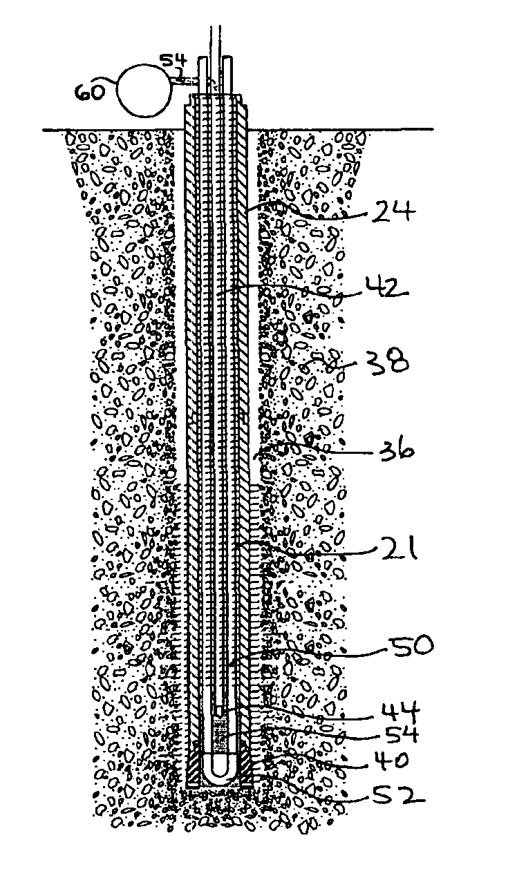
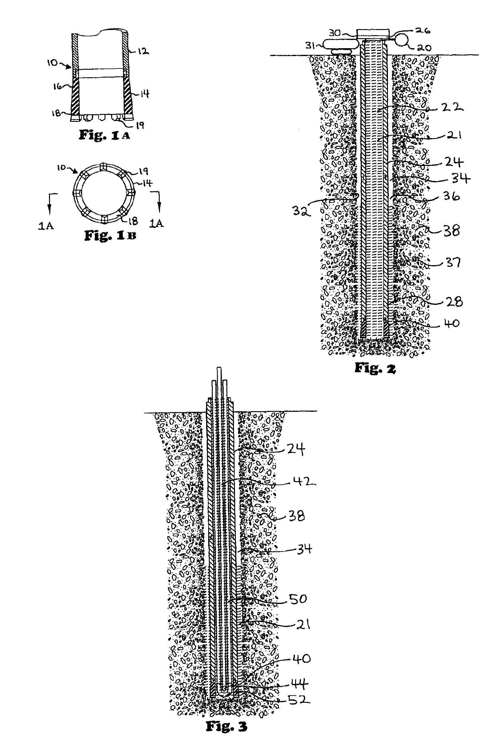
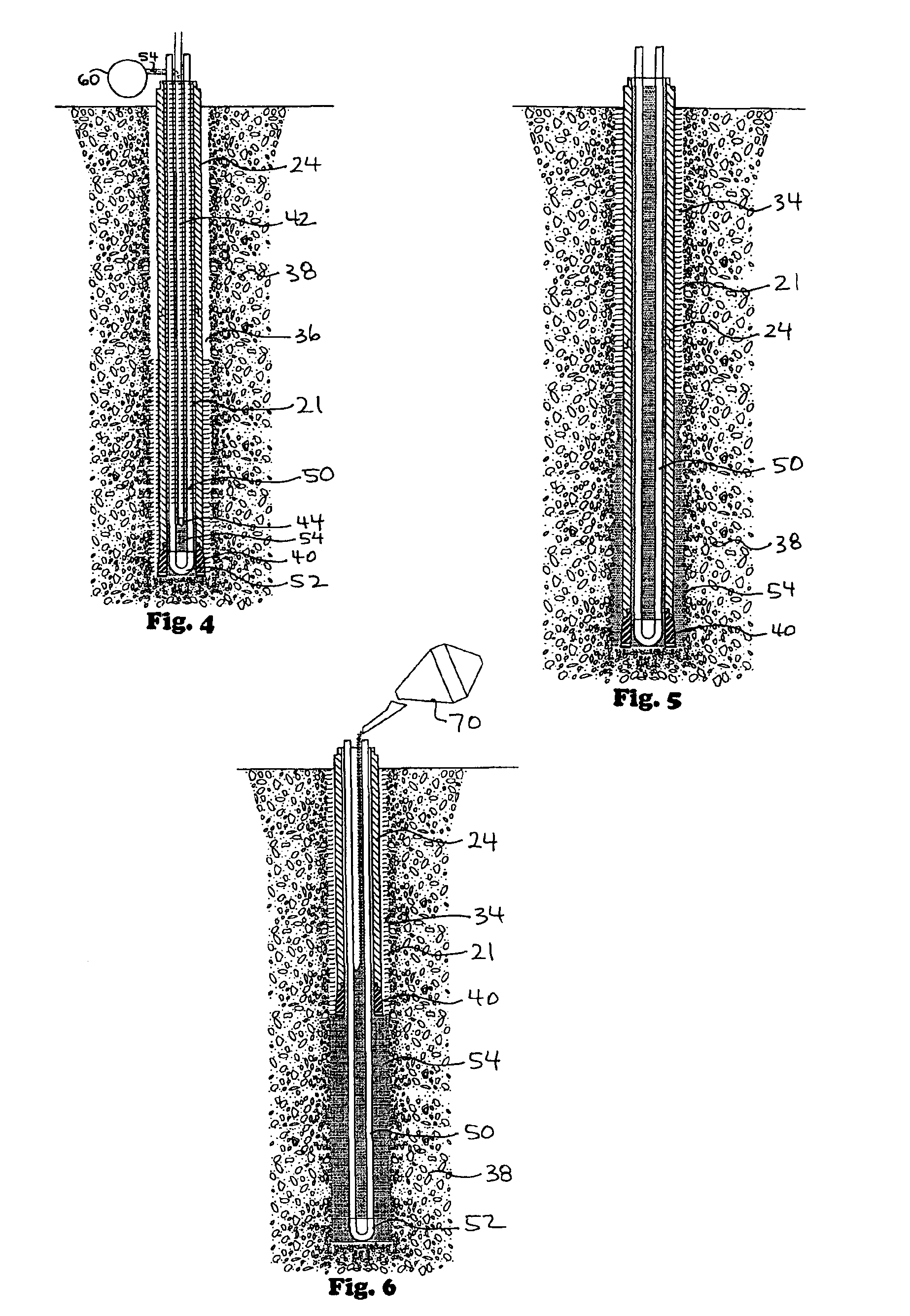
[0027]In one embodiment, a system according to the present invention includes steps of: drilling; earth loop insertion; grouting; and casing recovery. In one particular drilling method according to the present invention a steel cased borehole 5 inches in diameter 350 feet deep in an unconsolidated formation (e.g., but not limited to, sandy clay) is drilled in 20 minutes if no unexpected drilling conditions are encountered. In one aspect the drilling rig is a crawler-mounted or truck-mounted machine. In one aspect only a single operator is required to perform the complete drilling and casing function.

[0028]In one embodiment a drilling machine according to the present invention has a sonic rotary drill head; an on-board carousel or magazine for both drill pipe and casing; an onboard water pump; an onboard air compressor; a drill mast to which is movably connected a sonic drilling head; movement apparatus for moving the sonic drilling head up and down (and casing connected thereto); an...


PUM


Abstract

A method for installing a heat exchange pipe loop in a borehole, the method in at least certain aspects, including drilling a borehole with a sonic drill system having a head and casing connected thereto, a drill shoe on a lower end of the casing movable by the sonic drill head to drill the borehole, pumping fluid (e.g., water and drilling fluid) into the casing, out through a lower end of the casing, and up to earth surface in an annular space in the borehole so that drilled material flows to the earth surface, lowering a heat exchange pipe loop down into the casing, introducing grout into the casing around the heat exchange pipe loop, and extracting the casing from the borehole.

Description

BACKGROUND OF THE INVENTION[0001]1. Field of the Invention[0002]The present invention is directed to underground heat exchange systems; to apparatus and methods for drilling wellbores for such systems using sonic drilling systems; and to installing underground heat exchange systems.[0003]2. Description of Related Art[0004]The prior art discloses a wide variety of systems for circulating water or refrigerant through pipes in the earth with the earth serving as a heat sink or heat source heat transfer between the fluid in the pipes and the earth. The prior art discloses numerous in-ground heat exchanger systems; and grouting systems (see, e.g. U.S. Pat. Nos. 5,435,387; 5,244,037; 5,261,251; 5,590,715; 5,758,724; 6,250,371; 6,041,862; and 6,276,438; and pending U.S. application Ser. No. 10 / 387,125 filed Mar. 12, 2003; and the references cited in these patents and application)—all of which patents, applications therefor, references and application are incorporated here fully for all pur...

Claims


Application Information

Patent Timeline
Patent Type & Authority Patents(United States)
IPC IPC(8): E21B7/00E21B27/00E21B7/24E21B33/13F24J3/00F24J3/08
CPCE21B7/24E21B33/13F24J3/083F24J3/086F24J2003/088Y02E10/125Y02E10/16F24T10/30F24T2010/53F24T10/15Y02E10/10
Inventor JOHNSON, JR., HOWARD E.
Owner ENLINK GEOENERGY SERVICES
Why Eureka
Try Eureka