Pneumatic module

Inactive Publication Date: 2005-10-18
DELPHI TECH INC
View PDF15 Cites 17 Cited by
  • Summary
  • Abstract
  • Description
  • Claims
  • Application Information

AI Technical Summary

Benefits of technology

[0007]In one aspect of the invention, a pneumatic module is provided that includes an actuator assembly and a manifold. The actuator assembly includes a main body having a bore, an armature, a primary plate, a secondary plate, a coil, an electrical terminal and a frame. The manifold includes a valve seat, a control port and a supply port. When the actuator is in a de-energized state, a compressed spring forces the armature against the valve seat, sealing off the supply port from the control port. The end of the armature in contact with the valve seat has a seal configured to increase the actuator's ability to maintain low leakage in both flow directions relative to the known art. The valve seat is shaped such that it protrudes toward the bore. This arrangement improves the ability to maintain low leakage in both flow directions, especially from the control port to the supply port.
[0008]When the actuator is in an energized state, current flows through the coil, thereby generating a magnetic field. The magnetic field forces the armature away from the valve seat toward the primary plate. Once the armature moves sufficiently toward the primary plate, the valve seat becomes unsealed, thus allowing fluid flow between the supply port and the control port. An end of the armature proximate to the primary plate has an endcap to minimize and dampen the mechanical noise gen

Problems solved by technology

However, a problem generally encountered in the pneumatic module field involves providing a device to simultaneously meet the requirements of low internal leakage in both fluid flow directions, high operating pressure, low noise, low cost and ease of assembly.
Pneumatic modules having low internal leakage in only one flow direction are inefficient in systems requiring effective sealing to prevent fluid backflow.
Such interna

Method used


Image

  • Pneumatic module
  • Pneumatic module
  • Pneumatic module

Examples


Embodiment Construction

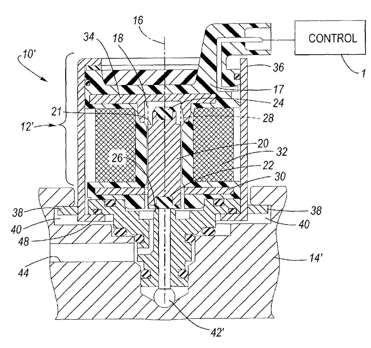
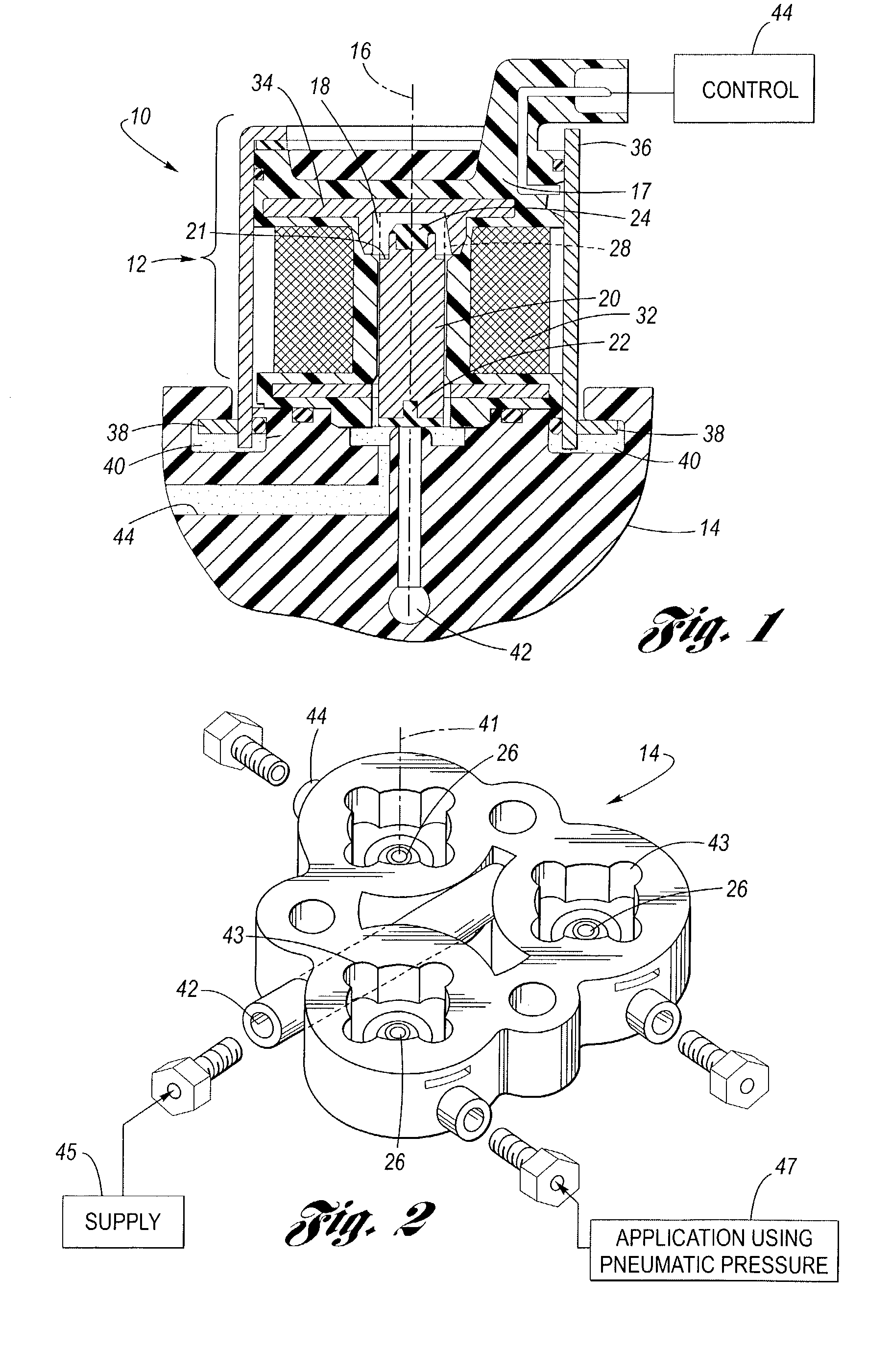
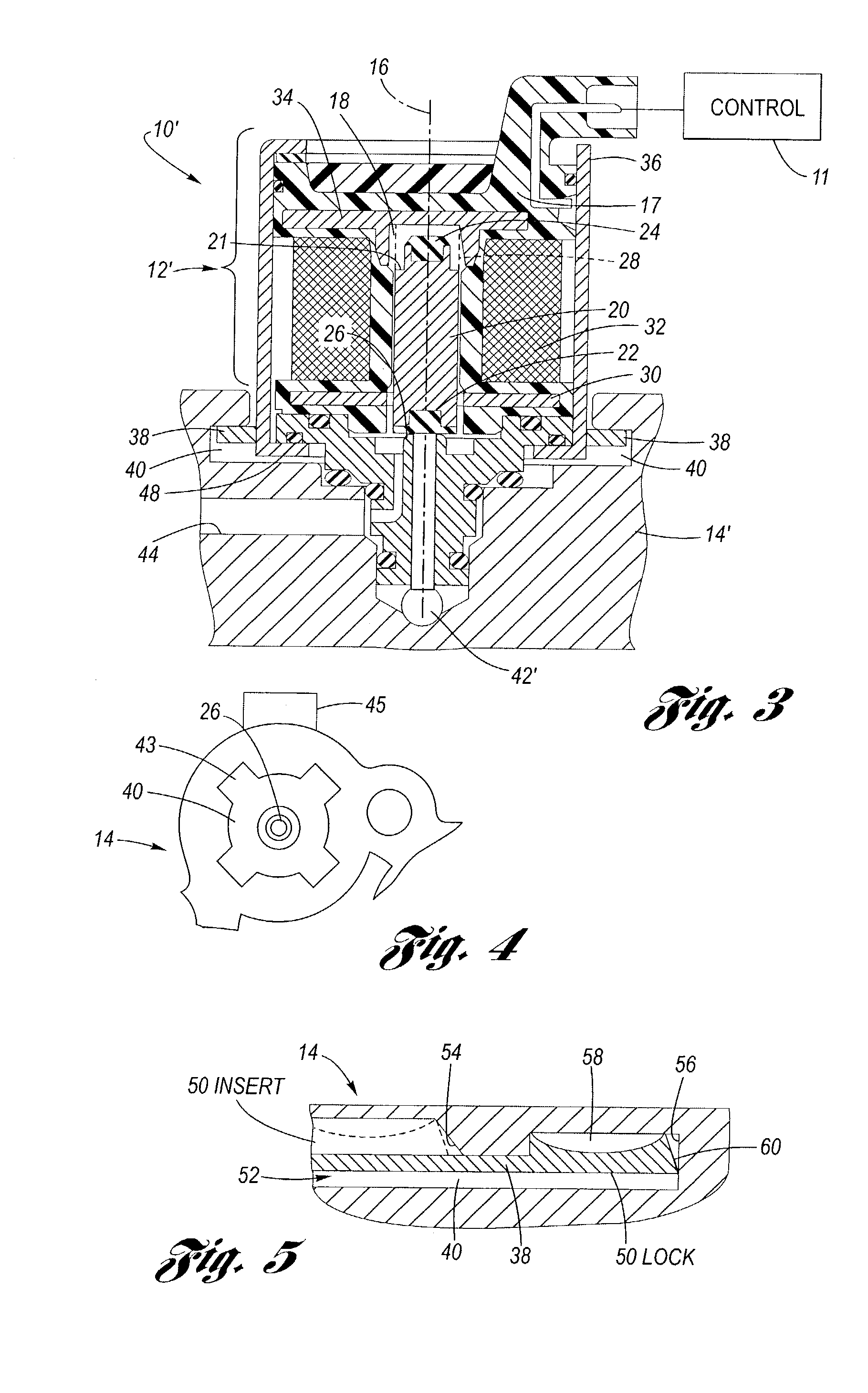
[0018]Referring now to the drawings wherein like reference numerals are used to identify identical components in the various views, FIG. 1 illustrates one embodiment of a pneumatic module 10 having an actuator assembly 12 and a manifold 14. Actuator assembly 12 is generally configured for selective control of fluid flow through manifold 14. Manifold 14 is generally configured to provide the combination of input / output parts for allowing such fluid flow.

[0019]Actuator assembly 12 is centered about an axis 16 and has a main body 17 that is similarly centered about axis 16. Main body 17 has a blind bore 18 within which an armature 20 resides. Both bore 18 and armature 20 are centered about axis 16. Armature 20 is made from a ferromagnetic material and includes an annular shoulder 21. The shape of armature 20 can be altered to meet design requirements and thus is not limited to the exemplary shape illustrated in FIG. 1. Armature 20 extends along axis 16 within bore 18 and has a seal 22 ...


PUM


Abstract

A pneumatic module includes an actuator assembly and a manifold. The actuator assembly includes a main body having a bore, an armature, overmolded primary and secondary plates, a coil and a frame. The manifold includes a valve seat, a control port and a supply port. When the actuator is in a de-energized state, the armature is forced against the valve seat by a spring, sealing off the supply port from the control port. When the actuator is in an energized state, current flows through the coil, thereby generating a magnetic field. The magnetic field forces the armature to move toward the primary plate, causing the valve seat becomes unsealed. Once the valve seat is unsealed, fluid flow is permitted between the supply port and the control port. The one end of the armature has an endcap to minimize mechanical noise generated by movement of the armature against the spring. The frame surrounding the actuator assembly has flanges extending from both ends. These flanges correspond to wells located within the manifold. The flanges and wells are configured such that when the flanges are inserted into the wells, the actuator assembly can be twisted and locked into the manifold without requiring additional traditional fasteners, such as bolts or screws.

Description

BACKGROUND OF THE INVENTION[0001]1. Technical Field[0002]The present invention is directed generally to modules, and, in particular, to pneumatic modules.[0003]2. Description of the Related Art[0004]It is known to provide a pneumatic module configured to selectively control the flow of fluid from a first port to a second port, as seen by reference to U.S. Pat. No. 6,409,145 to Fong et al (“Fong”). Fong discloses an armature in combination with a valve seat to implement this fluid control. However, a problem generally encountered in the pneumatic module field involves providing a device to simultaneously meet the requirements of low internal leakage in both fluid flow directions, high operating pressure, low noise, low cost and ease of assembly. Pneumatic modules having low internal leakage in only one flow direction are inefficient in systems requiring effective sealing to prevent fluid backflow. Such internal leakage is often caused by the failure of the armature to make effective ...

Claims


Application Information

Patent Timeline
IPC IPC(8): F16K31/06
CPCF16K31/0651F16K31/0655F16K31/0693F16K31/0696Y10T137/5987
Inventor WEBER, ALEXIS C.MORENO, ALEJANDRO
Owner DELPHI TECH INC
Why Eureka
Try Eureka