Vehicle door controlling apparatus

a technology for controlling apparatus and sliding doors, which is applied in the direction of doors, lock applications, roofs, etc., can solve the problems of insufficient the door connecting mechanism interferes with the opening and closing of sliding doors, etc., and achieves the effect of improving the mechanical strength of the vehicl

Inactive Publication Date: 2005-10-18
AISIN SEIKI KK
View PDF14 Cites 39 Cited by
  • Summary
  • Abstract
  • Description
  • Claims
  • Application Information

AI Technical Summary

Benefits of technology

[0008]The vehicle includes doors, which open and close in the forward and backward directions of the vehicle and removes the center pillar that is generally installed between the front and rear doors. As a result, an entrance of the vehicle becomes so wide that an ascending and descending property or a stacking property to the vehicle can be improved. In addition, the first locking device (which becomes the door connecting mechanism) for connecting a swinging door and a sliding door is installed and the front and rear doors are connected through the first locking device so that the mechanical strength of the vehicle can be improved.

Problems solved by technology

However, when the above-described configuration is applied to a sliding door system (which is referred to as a power sliding door system) for connecting the swinging door to the sliding door and electrically operating the sliding door, if the sliding door does not take into consideration whether the locking device of the swinging door, which controls the movement of the sliding door, is in lock state in which the movement of the sliding door is locked by a locking device of the swinging door, the door connecting mechanism interferes with the opening and closing of the sliding door.
For example, if interference occurs, the sliding door is opened where the lock state is unstable and the sliding door is not well opened.

Method used


Image

  • Vehicle door controlling apparatus
  • Vehicle door controlling apparatus
  • Vehicle door controlling apparatus

Examples


Embodiment Construction

[0028]Hereinafter, an embodiment of the present invention will be described in detail with reference to the accompanying drawings.

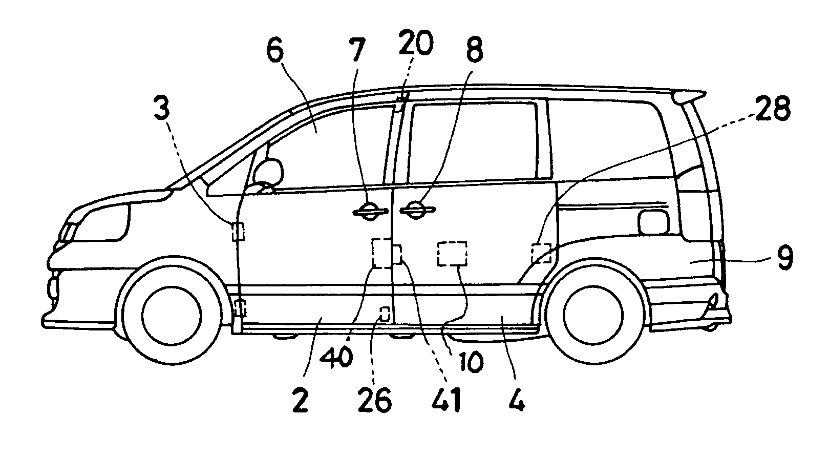
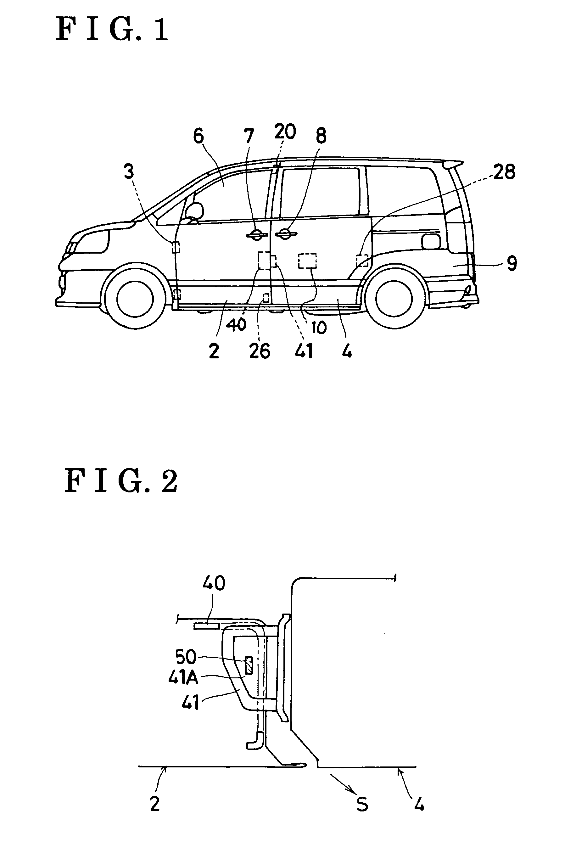
[0029]FIG. 1 is a side view of a vehicle on which a vehicle door controlling apparatus 1 is mounted. The vehicle has an opening 6 which an occupant ascends and descends at the side of the vehicle in its widthwise direction and the opening 6 is closed by two vehicle doors. A swinging door 2 for opening and closing the opening of the vehicle in its widthwise direction is installed at the front side of the opening 6 so as to be capable of being opened and closed with respect to a vehicle body 9. In addition, a sliding door 4 for opening and closing the opening of the vehicle in its forward and backward directions is installed at the rear side of the opening 6 so as to be capable of being opened and closed with respect to the vehicle body 9. Thus, the vehicle is configured as a center pillarless vehicle, which has no center pillar for partitioning the opening...


PUM


Abstract

A vehicle door controlling apparatus comprises a connection locking mechanism between a swinging door and a sliding door for locking the two doors by connecting them to each other. The swinging door is capable of opening or closing the front side of a vehicle opening and the second door is capable of opening or closing the rear side of the opening. The vehicle door controlling apparatus further comprises an operating switch which requests the opening of the sliding door, a rotary switch which detects a lock state between the doors, and a latch switch and a pole switch which detect a lock state at the rear side of the sliding door. When the controller detects a request for opening the sliding door, a release actuator releases the lock state, electric current is applied to a sliding motor, and electrical operation of the sliding door starts.

Description

CROSS-REFERENCE TO RELATED APPLICATIONS[0001]This application is based on and claims priority under 35 U.S.C. §119 with respect to Japanese Application No. 2003-117215 filed on Apr. 22 2003, the entire contents of which are incorporated herein by reference.BACKGROUND OF THE INVENTIONS[0002]1. Field of the Inventions[0003]The present invention relates to a vehicle door controlling apparatus that electrically operates vehicle doors to perform opening / closing thereof, and more specifically, for a center pillar-less vehicle, to an apparatus for controlling a sliding door, which includes a swinging door for performing opening / closing thereof in the widthwise direction of the vehicle and a sliding door for performing opening / closing thereof in the backward and rearward direction of the vehicle.[0004]2. Description of the Related Art[0005]Conventionally, a vehicle which includes a turning door (swinging door) which is opened or closed in the widthwise direction thereof and a sliding door w...

Claims


Application Information

Patent Timeline
Patent Type & Authority Patents(United States)
IPC IPC(8): E05B65/20E05B65/36E05B65/08E05F15/14E05F15/20B60J5/00B60J5/04B60J5/06E05B77/24E05B77/46E05B81/72E05B83/36E05B83/38E05B83/40
CPCE05B65/0811E05B77/24E05B77/46E05B83/40E05Y2201/22E05F15/70E05Y2201/434E05Y2900/531E05F15/646E05Y2201/246Y10T292/1082
Inventor SUZUKI, SHINTAROIMAIZUMI, TOMOAKIITAMI, EIJI
Owner AISIN SEIKI KK
Why Eureka
Try Eureka