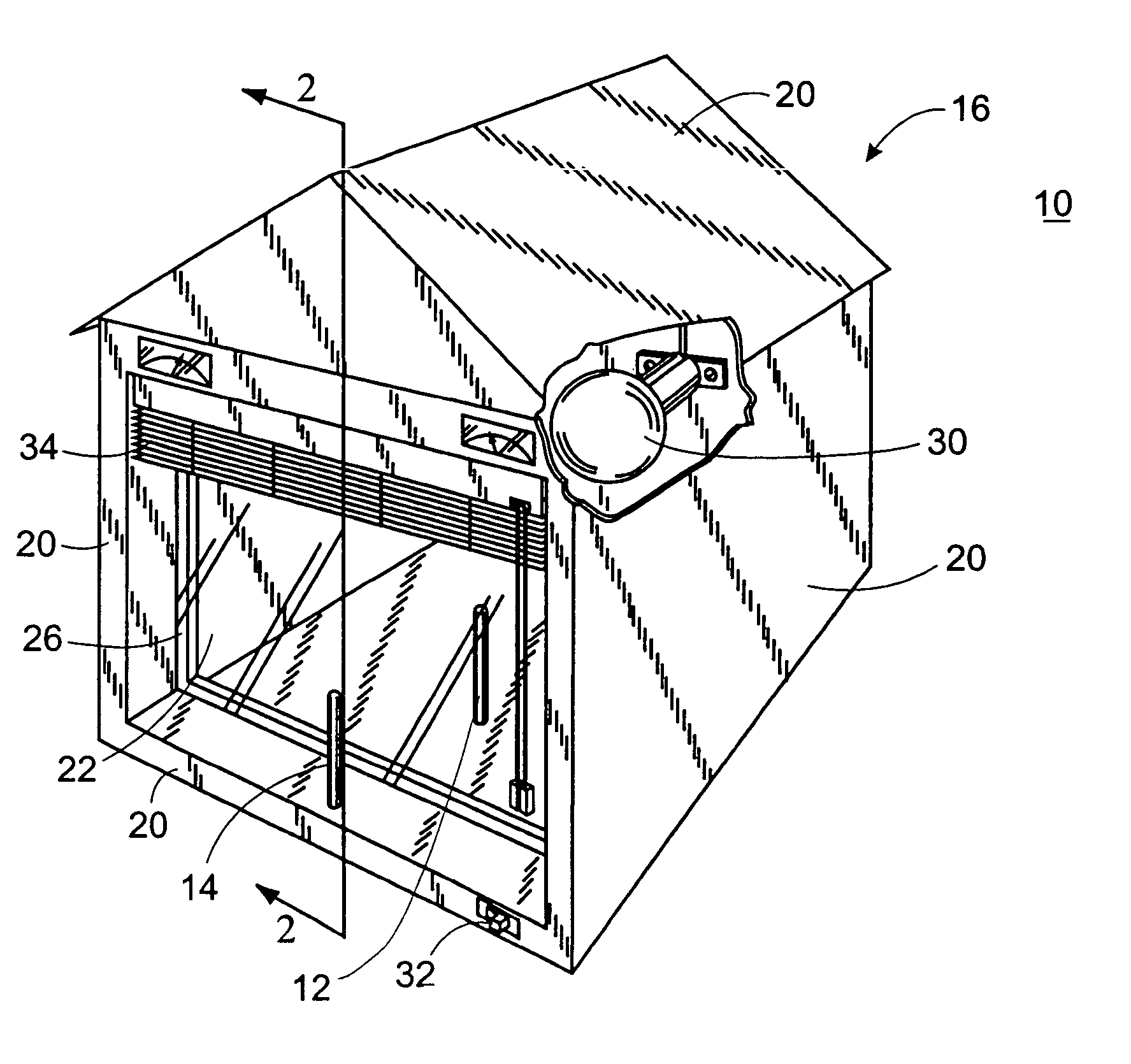
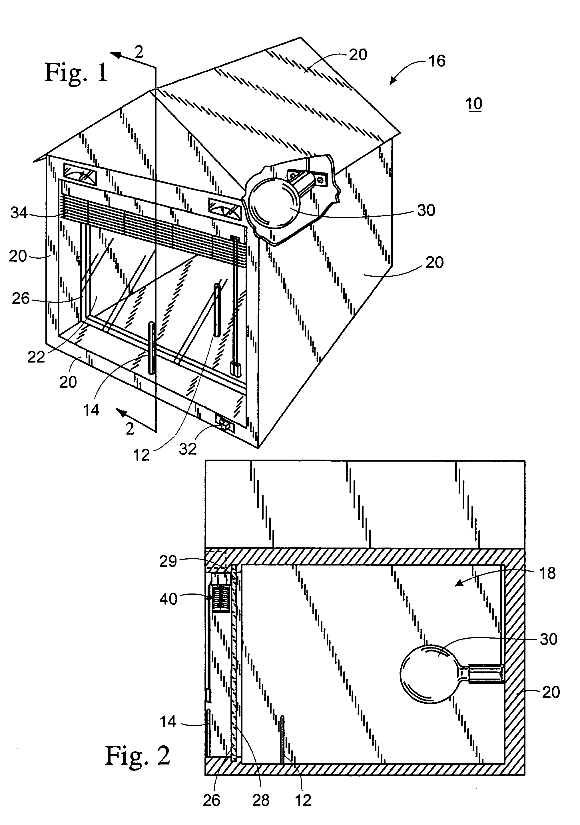
[0023]Referring now to the drawings wherein the showings are for purposes of illustrating preferred embodiments of the present invention only, and not for purposes of limiting the same. FIG. 1 perspectively illustrates a display device 10 constructed in accordance with a preferred embodiment of the present invention. As indicated above, the display device 10 enables a consumer to quickly observe and determine each window covering's heat insulation properties. Those of ordinary skill in the art will recognize that the display device 10 may be formed to have a variety of shapes, configurations, geometries, sizes and textures other than for that shown in the provided Figures.
[0024]Referring now to FIGS. 1 and 2, the display device 10 comprises a display housing 16. Although the display housing 16 is shaped in the form of a house, such depiction is exemplary in nature and should not be limited thereto. In particular, the display housing 16 defines an internal compartment 18. The internal compartment 18 is formed by a plurality of connected wall panels 20. More particularly, the panels 20 which are vertically erected from the walls of the display housing 16. Other panels 20 can be adjoined to vertically-erected panels 20 in any desired configurations in order to form other parts of the display housing 16, such as its ceiling or floor, for example.
[0025]At least one of the panels 20 that form the walls of the display housing 16 may be characterized as a heat-conducting panel 22. The heat-conducting panel 22 is adapted to conduct heat therethrough at a greater rate than the rest of the wall panels 20.
[0026]In the preferred embodiment, the heat-conducting panel 22 is a glass panel 24 with a support frame 26 formed around its peripheral edges 28 which simulates a conventional glass window of a residential or commercial building. The glass panel 24 can be connected to other adjacent panels 20 via the support frame 26 thereof. The support frame 26 is preferably fabricated from a wooden material. Because it is recommended that the heat-conducting panel 22 conducts heat at a greater rate than others, other panels 20 should be formed from materials that are less heat conducting than the glass panel 24. For instance, the remaining panels 20 may be fabricated from a wooden material as it is generally incapable of conducting heat faster than the glass. Furthermore, for the reasons that will be discussed below, more than one of the vertically-erected wall panels 20, or even all of them, may be construed as heat-conducting panel 22 designed in the similar fashion above.
[0027]There is provided a heat source 30 disposed within the internal compartment 18 for the purpose of generating heat therein. Preferably, the heat source 30 is a light bulb that can be activated/deactivated by an electrically communicated external switch 32. However, it will be appreciated by those of ordinary skill in the art that other forms of heat source (e.g., heat lamps) may be utilized in lieu of the light bulb. The light bulb simulates the sun to produce radiant and convection which is conducted via the glass panel 24. In this respect, the internal compartment 18 is representative of an outside environment and thus stimulates its temperature. Simply, put, the heat source 30 can generate heat within the internal compartment 18 to a prescribed temperature as to represent the desired outside setting.
[0028]Referring more particularly to FIGS. 3–5, the display housing 16 is adapted to removably mount plural window coverings along its glass panel 24. To accomplish such objective, retaining members 36 are disposed about an upper peripheral edge 29 of the glass panel 24. Preferably, there are two brackets serving as the retaining members 36 which are positioned generally above the upper peripheral edge 29. The two brackets should be sufficiently and laterally separated from each other so as to respectively receive and maintain end portions 38 of the selected window covering 34 thereto. The brackets should be sufficient in size as to comfortably snap-on and snap-off the respective end portions 38 of the window covering 34.
[0029]The retaining members 38 position the window covering 34 above the upper peripheral edge 29 such that it may slide up and down between retracted and extended positions 40, 42. As such, the heat-conducting glass panel 24 is substantially exposed when the window covering 34 forms the retracted position 40. Or, the glass panel 24 is substantially covered when the window covering 34 slides down and forms the extended position 42. Obviously, it is recommended that the window covering 34 further be closed 44 when extended along the glass panel 24 in order to fully insulate the heat conducting therethrough. Further, when the window covering 34 retracts to the top, it should be open 45 so as to facilitate its transition.
[0030]Temperature measuring sensors 12, 14 are strategically positioned with respect to the display housing 16 such that the consumer can quickly and simultaneously observe and determine the temperature difference formed therebetween. One manner of achieving such objective is to place an inner temperature measuring sensor 12 within the internal compartment 18 and an outer temperature measuring sensor 14 outside of the internal compartment 18 adjacent the heat-conducting glass panel 24. Preferably, the inner and outer temperature measuring sensors 12, 14 are thermometers. Even more preferably, they are laser thermometers.
[0031]The outer temperature measuring sensor 14 should be sufficiently distant from the glass panel 24 such that the window covering 34 can be disposed therebetween when extended. Alternatively, the outer temperature measuring sensor can be a manual hand held sensor. In this way, a simulation of an inside setting of a residential and/or commercial building may be duplicated (i.e., sunlight hitting the window covering from outside towards the inside of the residential and/or commercial building).
[0032]In operation, a window covering 34 may be selected by a consumer to evaluate its heat insulation effectiveness. The consumer may choose a window covering 34 from a wide selection. Such selection may comprise a fabric blind, a vertical blind, a wood blind, a metal blind, a pleated shade, and a cellular shade. However, other types of blinds can be incorporated into the selection. The end portions 38 of the selected window covering can then be engaged/snapped into the retaining members 36. When engaged therein, the window covering 34 can be extended to substantially cover the entirety of the glass panel 24. Further, such window covering 34 should be closed so as to properly insulate the heat conducting through the glass panel 24 from within the internal compartment 18.
[0033]When the internal compartment 18 is heated to a prescribed temperature (e.g., 90 degrees Fahrenheit). The consumer can easily and rapidly observe that temperature by looking at the inner temperature measuring device 12. Simultaneously, the consumer can further look at the outer temperature measuring device 14 as the extended window covering 34 is disposed between it and the glass panel 22. In this regard, the consumer is able to visually observe, first-hand, the insulation property of the selected window covering 34 by comparing the temperature difference therebetween. Of course, the window covering 34 may be conveniently removed thereafter so that a different window covering 34 may be mounted to determine its insulation effectiveness via the similar process.
[0034]As explained above, the display device 10 may have more than one heat-conducting panel 22 so that a number of window coverings' insulation properties may be measured simultaneously. When there are more than one heat-conducting panel 22, the consumer can simply engage an equal or less number of window coverings 34 thereto similar to the manner specified above to insulate the heat conducting respectively therethrough. By positioning an outer temperature measuring sensor 14 adjacent to each of the extended window coverings 34, a number of insulation properties can be simultaneously evaluated.
[0035]Additional modifications and improvements of the present invention may also be apparent to those of ordinary skill in the art. Thus, the particular combination of parts described and illustrated herein is intended to represent only certain embodiments of the present invention, and is not intended to serve as limitations of alternative devices within the spirit and scope of the invention.