Separation device having a centrifugal rotor

a centrifugal rotor and separation device technology, which is applied in the direction of centrifuges, rotary centrifuges, maintenance and safety accessories, etc., can solve the problems of reducing the pumping effect of the inlet member, undesired large parts, and inability to keep the liquid surfa

Inactive Publication Date: 2005-10-18
ALFA LAVAL AB
View PDF26 Cites 23 Cited by
  • Summary
  • Abstract
  • Description
  • Claims
  • Application Information

AI Technical Summary

Benefits of technology

[0006]By the invention it is possible to minimise the surface of the rotatable inlet member being in contact with the liquid to be cleaned, irrespective of at which level the liquid surface is present. Thereby, rotation of the liquid present in the container and which is to be pumped upwardly through the inlet member is minimized. Furthermore, the invention avoids liquid being pumped upwardly on the outside of the inlet member as a consequence of the rotation of the liquid.
[0009]To achieve the best possible preconditions, as to function, for the sealing device when the centrifugal rotor is suspended from a flexible suspension device, the non-rotatable wall is suspended from the same flexible suspension device as the centrifugal rotor. In this way relative pendulum movements between the rotatable inlet member and the non-rotatable wall are avoided during operation of the centrifugal rotor.

Problems solved by technology

Often it is not possible to keep the liquid surface in a container for liquid to be cleaned constantly at a predetermined level.
Since the inlet member has to extend under the liquid surface, when the liquid is at a relatively low level, this means that an undesired large part of the inlet member will be immersed in the liquid when the liquid surface is at a relatively high level.
This reduces the pumping effect of the inlet member and causes undesired splitting of particles, which later are to be separated from the liquid in the centrifugal separator.
Another reason is that an unreasonably high amount of energy is required to operate the centrifugal rotor.

Method used


Image

  • Separation device having a centrifugal rotor
  • Separation device having a centrifugal rotor
  • Separation device having a centrifugal rotor

Examples


Embodiment Construction

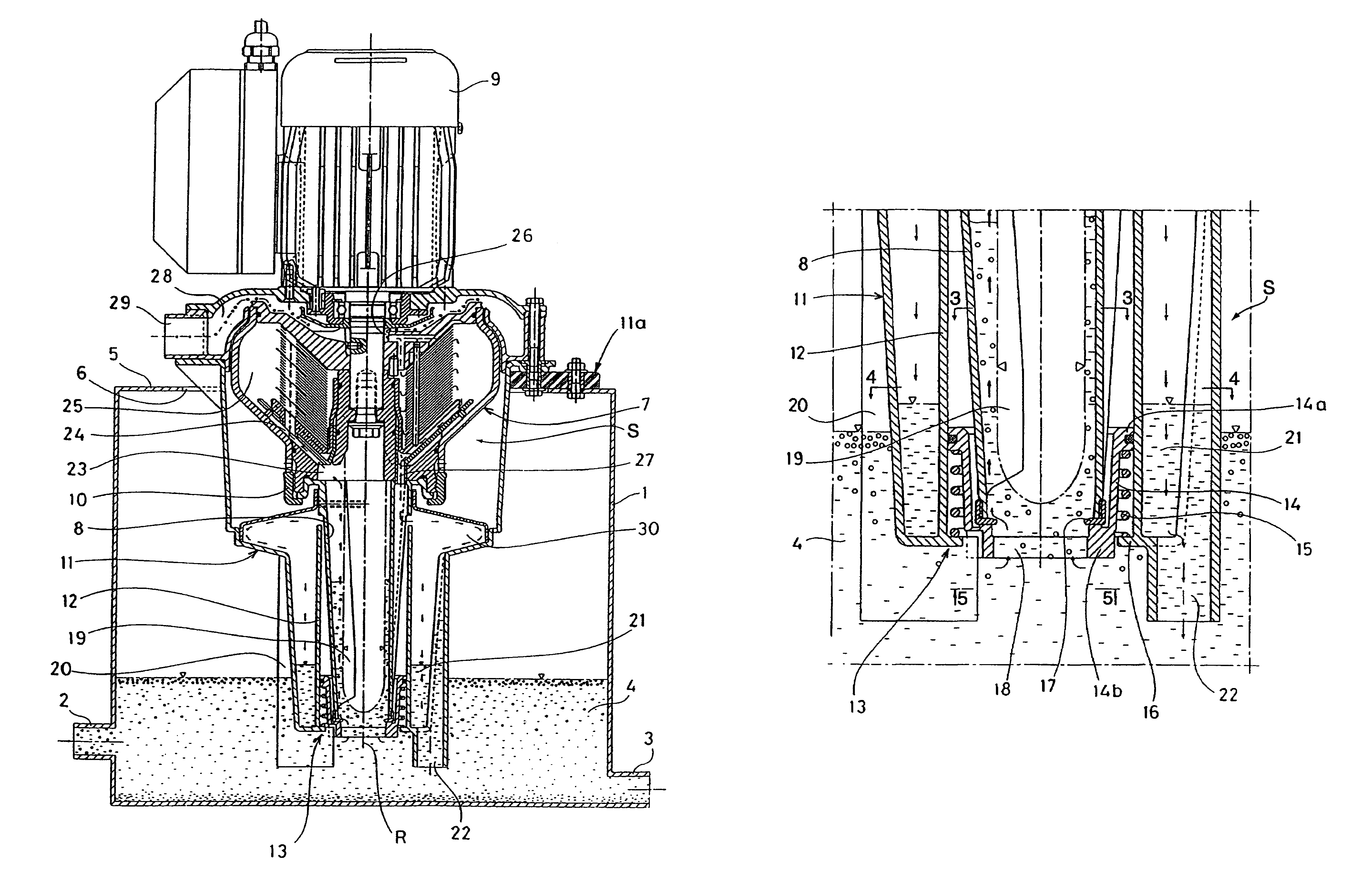
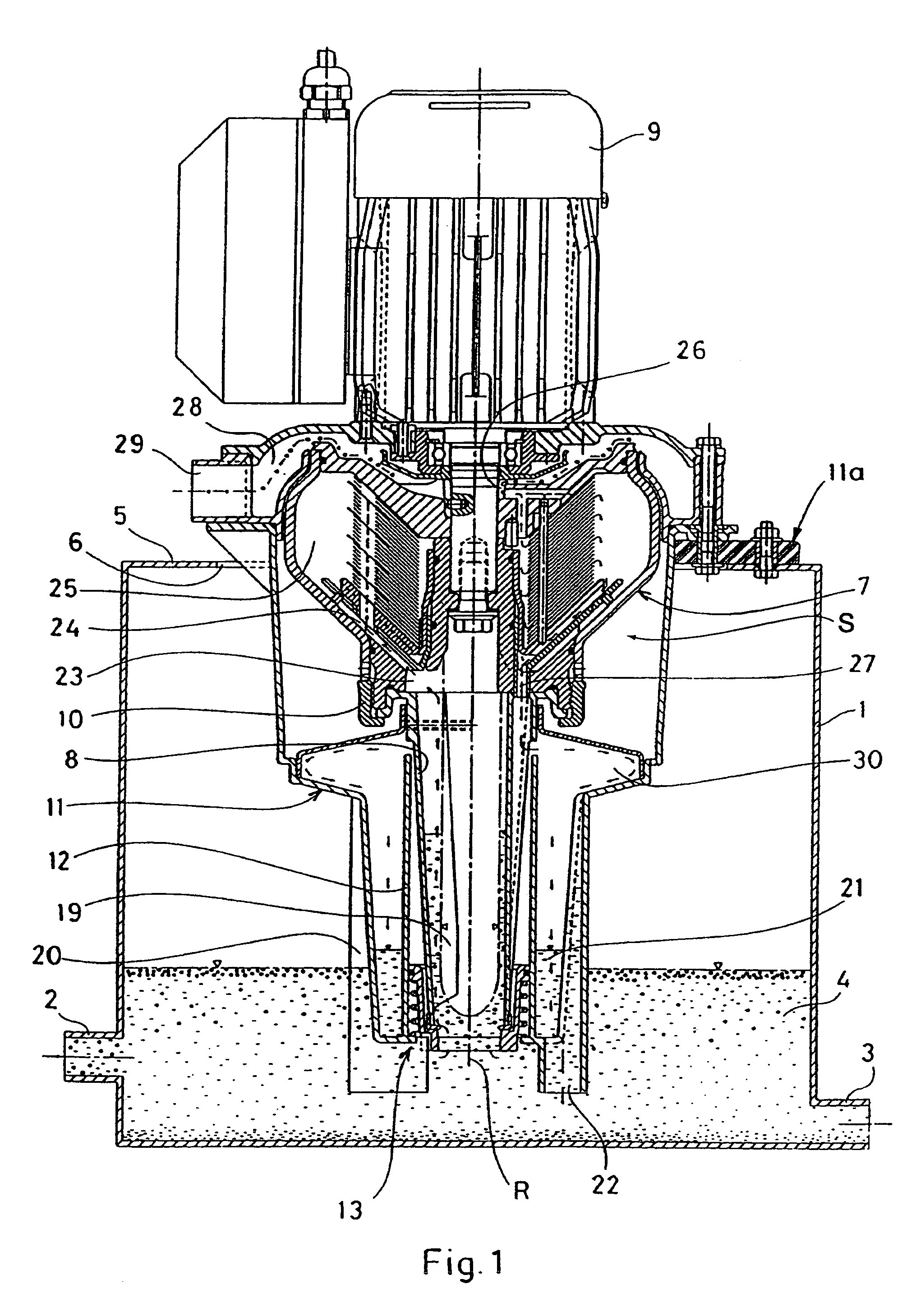
[0016]FIG. 1 shows a container 1 having an inlet 2 for liquid to be cleaned and an outlet 3 for liquid having been cleaned from particles suspended therein. In the container 1 there is a liquid body 4, in which some relatively light particles have accumulated in a surface layer and some relatively heavy particles have accumulated in a bottom layer.

[0017]The container 1 has an upper wall 5 having an opening 6. On the wall 5 there is mounted a centrifugal separation device according to the invention and indicated generally by the letter S, which extends down into the container. The separation device S includes a centrifugal rotor 7, an inlet member 8 connected with the centrifugal rotor and a motor 9 for rotation of the centrifugal rotor 7 and the inlet member 8 around a vertical rotational axis R.

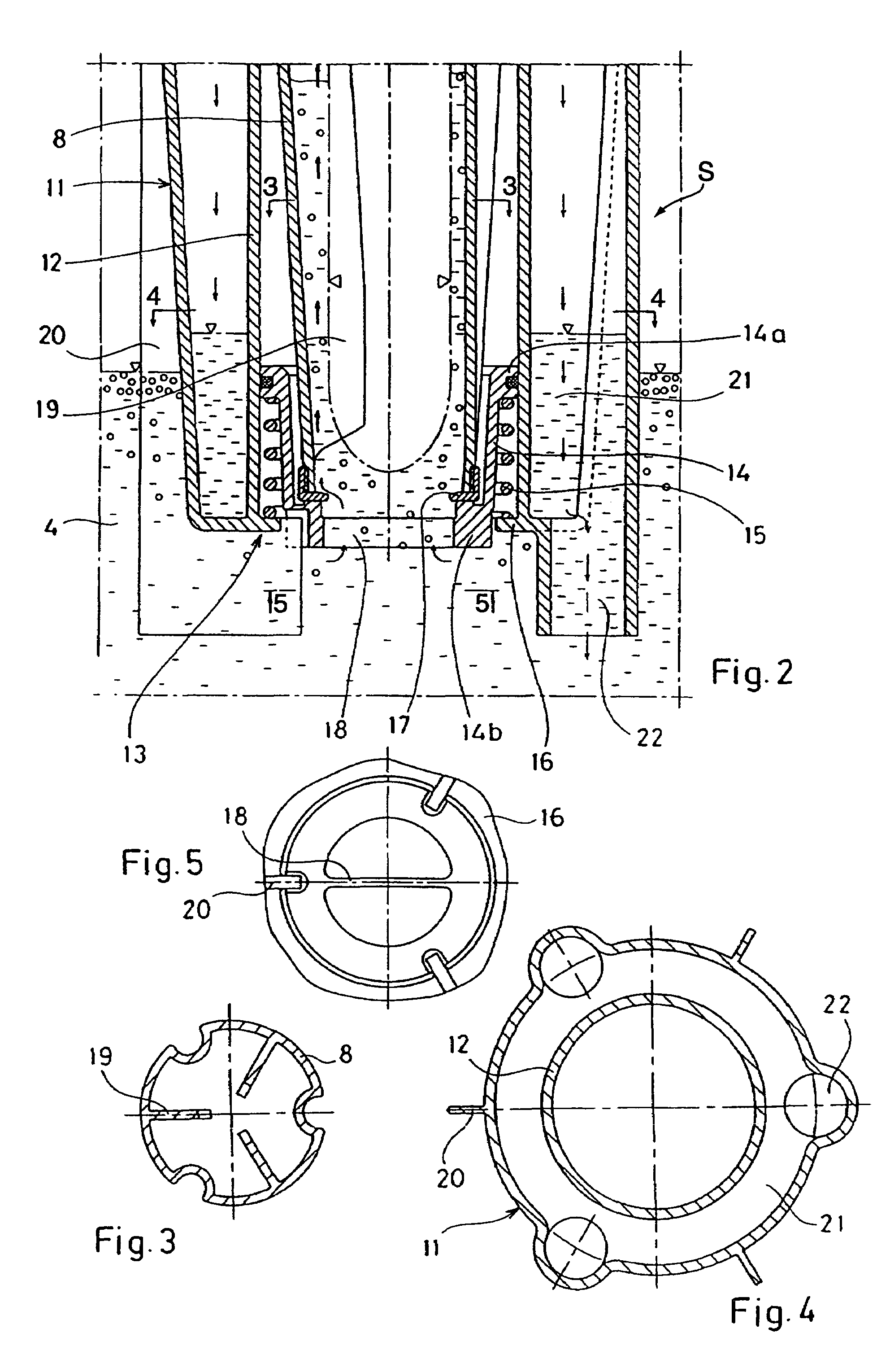
[0018]The inlet member 8, which is tubular and slightly conical, is connected with the centrifugal rotor by means of a lock ring 10 and extends downwards into the container 1, so that it is ...


PUM


Abstract

In a separation device for separating particles from a liquid, which is present in a container, a centrifugal rotor is rotatable around a vertical rotational axis. The centrifugal rotor has a tubular inlet member, which extends down into liquid to be treated and which upon rotation of the centrifugal rotor forms a pumping member adapted to pump liquid upwardly and into the centrifugal rotor. The rotatable inlet member is surrounded by a non-rotatable wall, a sealing device being adapted to seal between the rotatable inlet member and the non-rotatable wall. Thereby is avoided that liquid is pumped upwardly on the outside of the inlet member. Furthermore, a smallest possible part of the outside of the inlet member can be in contact with liquid, independent of the level of the liquid surface in the container.

Description

FIELD OF THE INVENTION[0001]The present invention relates to a centrifugal separation device for cleaning of a liquid from solid or liquid particles suspended therein and being lighter and / or heavier than the liquid, the separation device including a centrifugal rotor adapted to rotate around a vertical rotational axis, a driving device adapted for rotation of the centrifugal rotor around said rotational axis and a tubular inlet member which is connected with the centrifugal rotor and adapted to extend downwards from the centrifugal rotor and into a body of said liquid which is to be pumped by means of the inlet member into the centrifugal rotor.BACKGROUND OF THE INVENTION[0002]A separation device of this kind is known for instance through U.S. Pat. No. 1,927,822, U.S. Pat. No. 3,424,375 or EP 0 047 677 A2. The separation device can be applied directly onto a container containing the liquid to be cleaned.[0003]Often it is not possible to keep the liquid surface in a container for li...

Claims


Application Information

Patent Timeline
Patent Type & Authority Patents(United States)
IPC IPC(8): B04B11/00B04B11/02B04B1/00F04D1/14F04D1/00F16J15/16B04B1/08B04B7/02B04B9/00B23Q11/10
CPCB04B1/00B04B11/02F04D1/14
Inventor MONTANO, JESUSRIDDERSTRALE, ROLFSTROUCKEN, KLAUS HANS DIETER
Owner ALFA LAVAL AB
Why Eureka
Try Eureka