
Heat transfer segment for a cryoablation catheter

Inactive Publication Date: 2005-10-18
CRYOCOR
View PDF64 Cites 7 Cited by
  • Summary
  • Abstract
  • Description
  • Claims
  • Application Information

AI Technical Summary

Benefits of technology

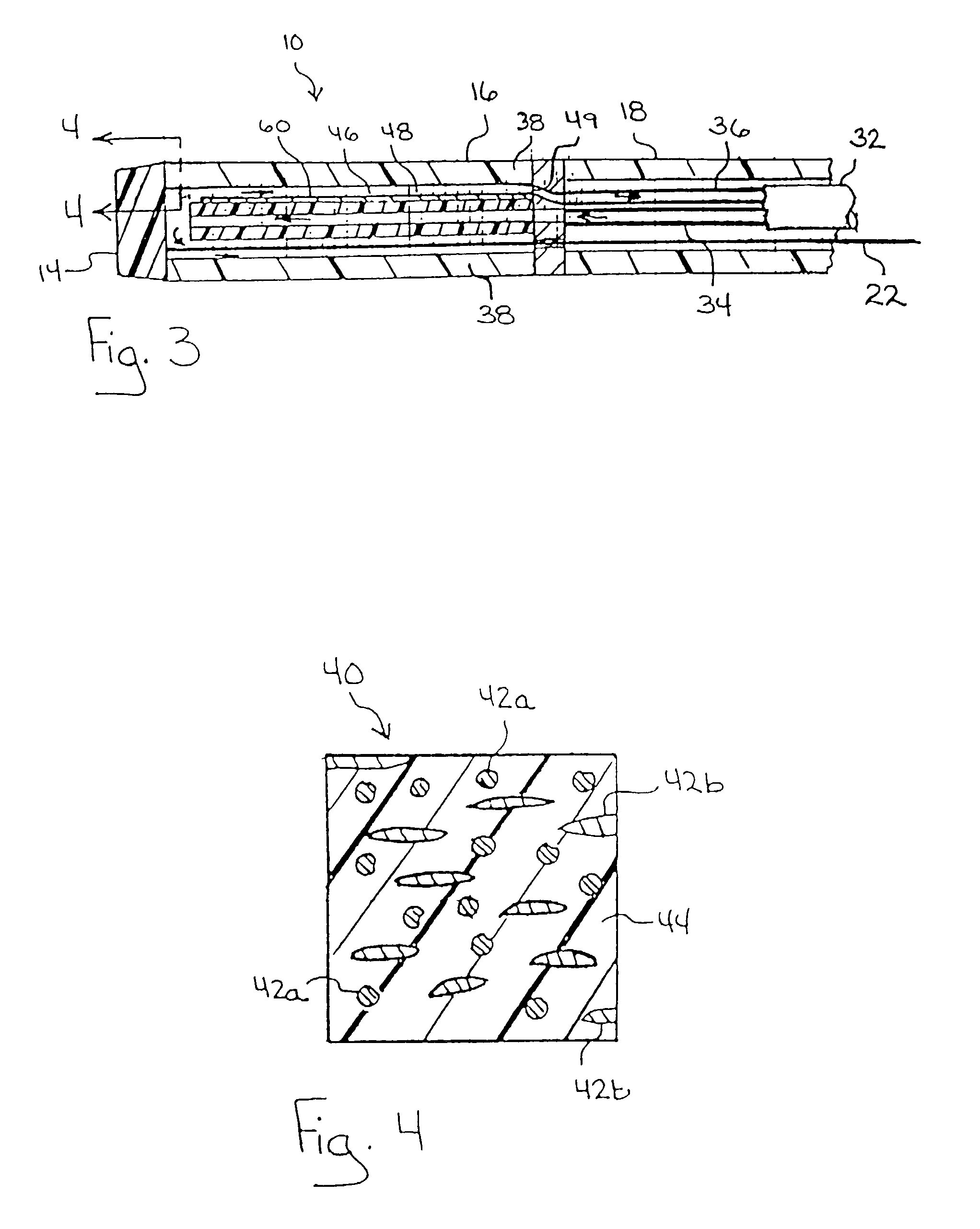
[0011]In a particular embodiment of the present invention, the member is shaped as an elongated tube having a lumen. At least one portion of the tube is made of the composite material while the remaining portion of the tube is made of the polymeric matrix material. For the present invention, the entire tube can be made of the composite material or only a portion. Typical portion shapes can include, but are not limited to an annular portion of the tube, an elongated portion of the tube that extends substantially parallel to the direction of tube elongation and a spot shape at a pre-selected location on the tube. It is to be appreciated that the shape and location of the composite portion will determine the amount and location of tissue that will be cryoablated when a refrigerant is disposed within the lumen of the tube.

Problems solved by technology

On the other hand, for applications wherein a significantly increased electrical conductivity is undesirable, a suitable composite material can be formulated, for example, by using a ceramic in the filler material.

Method used


Image

  • Heat transfer segment for a cryoablation catheter
  • Heat transfer segment for a cryoablation catheter
  • Heat transfer segment for a cryoablation catheter

Examples


Embodiment Construction

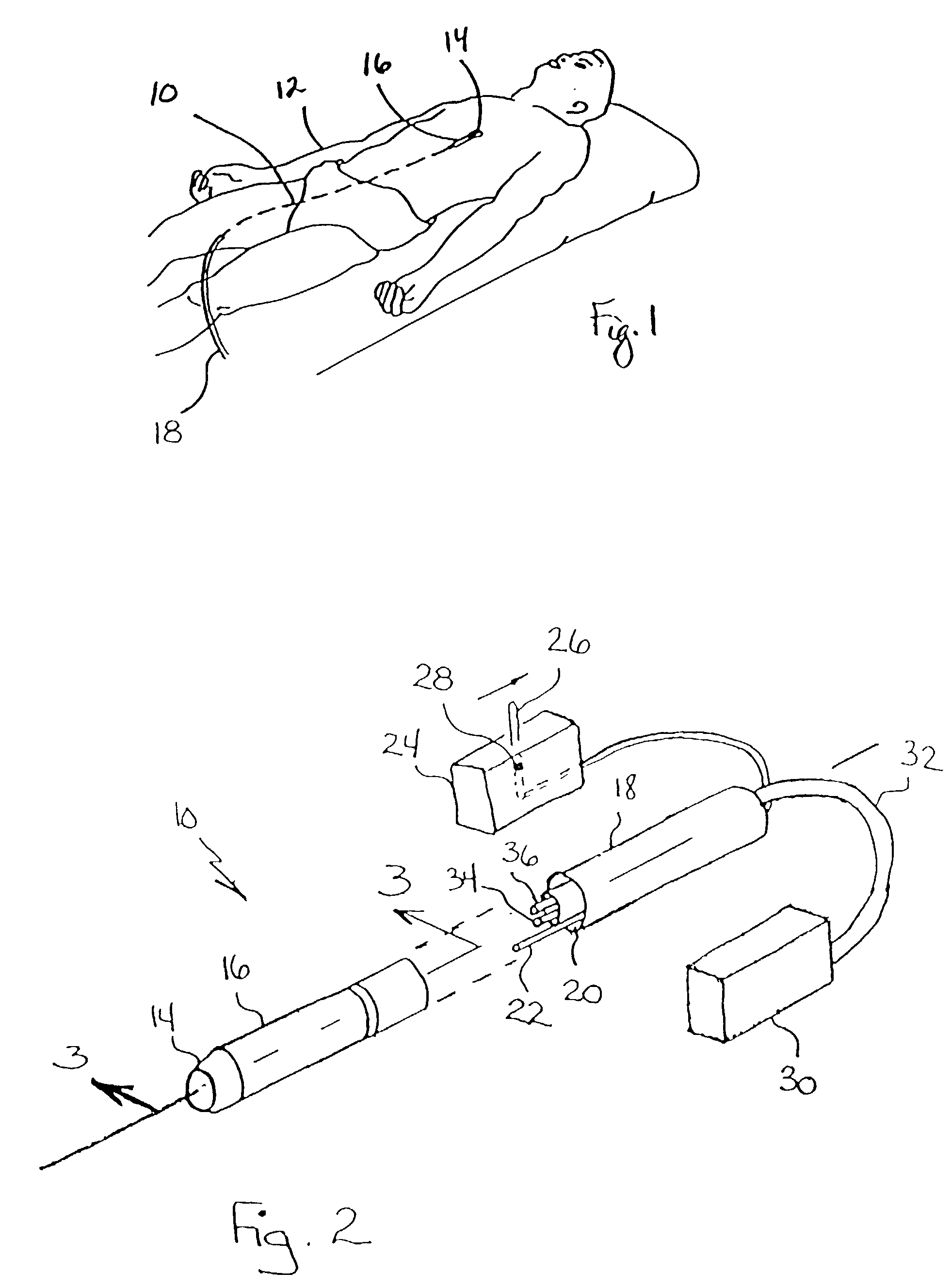
[0021]Referring initially to FIG. 1, a catheter for cryoablating internal target tissue in accordance with the present invention is shown and is designated 10. In FIG. 1, the catheter 10 is shown as it is being positioned in the vasculature of a patient 12. As further shown, the catheter 10 includes a distal tip 14 that is located at the distal end of the catheter 10 and a heat transfer segment 16 that is attached proximal to the distal tip 14. Still further, a catheter tube 18 is attached proximal to the heat transfer segment 16. In use, the catheter 10 is advanced until the heat transfer segment 16 is positioned adjacent the target tissue. Once the catheter 10 is positioned, a low temperature refrigerant is then introduced into the heat transfer segment 16, causing heat to flow from the target tissue, through the heat transfer segment 16 and into the refrigerant. This results in the cryoablation of the target tissue.

[0022]Referring now to FIG. 2, it will be seen that the catheter ...


PUM

PropertyMeasurementUnit
weight percentaaaaaaaaaa

Abstract

A heat transfer segment for a cryoablation catheter includes a member, at least a portion of which is made of a thermally conductive composite material. The composite material includes a polymeric matrix material such as a polyether block amide (PEBA) and a filler material which can include metals, metal alloys, ceramics, carbon and combinations thereof. One particular composition for the composite material includes approximately twenty weight percent of filler material, with the balance being polymeric matrix material. The composite has a thermal conductivity that is significantly increased relative to the polymeric matrix material and a flexibility that is not significantly reduced relative to the polymeric matrix material. In use, the heat transfer segment is disposed within a patient's body and positioned adjacent target tissue. A refrigerant is then introduced into the heat transfer segment causing heat to flow from the target tissue, through the member and into the refrigerant.

Description

FIELD OF THE INVENTION[0001]The present invention pertains generally to catheters. More particularly, the present invention pertains to catheters for cryoablating internal tissue. The present invention is particularly, but not exclusively, useful as a segment of a cardiac cryoablation catheter for transferring heat from target tissue to a refrigerant.BACKGROUND OF THE INVENTION[0002]Atrial fibrillation is an irregular heart rhythm that adversely affects approximately 2.5 million people in the U.S. It is believed that at least one-third of all atrial fibrillation originates near the ostium of the pulmonary veins, and that the optimal treatment technique is to ablate these focal areas through the creation of circumferential or linear lesions around the ostia of the pulmonary veins.[0003]Heretofore, the standard ablation platform has been radio-frequency energy. However, radio-frequency energy technology is not amenable to safely producing circumferential lesions without the potential ...

Claims


Application Information

Patent Timeline
Patent Type & Authority Patents(United States)
IPC IPC(8): A61B18/02A61B18/00A61B17/00
CPCA61B18/02A61B2017/00243A61B2018/00095A61B2018/0212A61B2018/0262
Inventor LENTZ, DAVID J.
Owner CRYOCOR
Learn More