Fuel cell system, and method of protecting a fuel cell from freezing

a fuel cell and system technology, applied in the field of fuel cell systems, can solve the problems of cell may destroy the fuel cell, the energy required for protecting the fuel cell becomes very large, and the heater will operate for a long time, so as to reduce the amount of energy required, prevent water freezing, and reduce the effect of energy consumption

Inactive Publication Date: 2005-10-18
NISSAN MOTOR CO LTD +1
View PDF6 Cites 29 Cited by
  • Summary
  • Abstract
  • Description
  • Claims
  • Application Information

AI Technical Summary

Benefits of technology

[0007]JP-A-H7-169476 published by the Japanese Patent Office in 1995 discloses a method of protecting a fuel cell from the freezing of water by keeping the fuel cell warm. This method prevents the freezing of the water in the fuel cell by warming the fuel cell using a heater, so that the temperature of the fuel cell does not fall below 0° C. However, by this method, if the fuel cell stops running for a long time, the heater will operate for a long time, and the energy required for protecting the fuel cell becomes very large.
[0008]It is therefore an object of this invention to protect a fuel cell from the freezing of water, and at the same time, reduce the amount of energy required for protection.
[0009]In order to achieve above object, this invention provides a fuel cell system, comprising a fuel cell having a water passage and a passage for gas required to generate power, a first protection device which prevents freezing of water in the fuel cell by maintaining the temperature of the fuel cell, a second protection device which prevents freezing of water in the fuel cell by draining water in the fuel cell, and a controller functioning to select one of the first protection device and second protection device as the protection device to be used when the fuel cell has stopped, and protect the fuel cell by operating the selected protection device when the fuel cell has stopped.
[0010]According to an aspect of this invention, this invention provides a method of protecting a fuel cell from freezing of water, comprising selecting one of a first protection method and a second protection method, preventing freezing of water in the fuel cell by maintaining the temperature of the fuel cell when the first protection method is selected, and preventing freezing of water in the fuel cell by draining the water in the fuel cell when the second protection method is selected.

Problems solved by technology

As the volume will expand relative to that of the water in the liquid phase if the water freezes, freezing of the water in the cell may destroy the fuel cell.
This method prevents the freezing of the water in the fuel cell by warming the fuel cell using a heater, so that the temperature of the fuel cell does not fall below 0° C. However, by this method, if the fuel cell stops running for a long time, the heater will operate for a long time, and the energy required for protecting the fuel cell becomes very large.

Method used


Image

  • Fuel cell system, and method of protecting a fuel cell from freezing
  • Fuel cell system, and method of protecting a fuel cell from freezing
  • Fuel cell system, and method of protecting a fuel cell from freezing

Examples


second embodiment

[0068]Next, a second embodiment will be described.

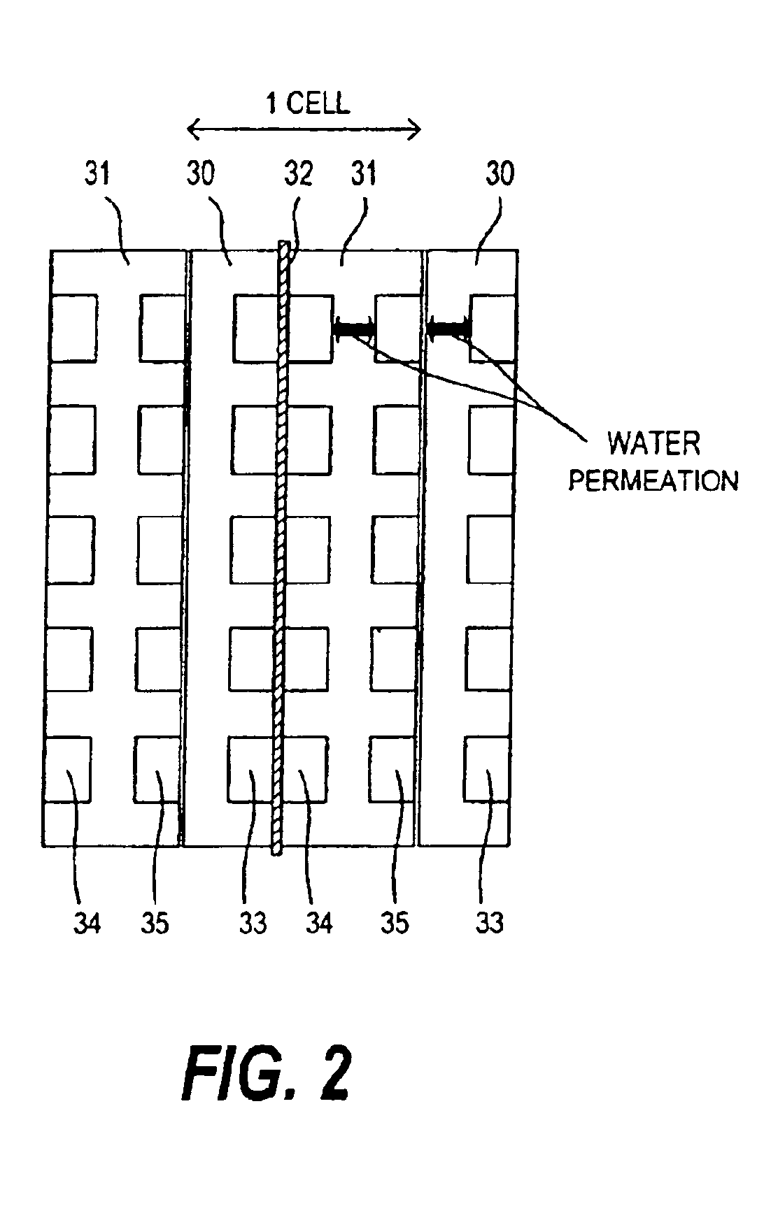
[0069]In the first embodiment, humidification of gas and recovery of water from the gas were performed in the fuel cell stack 1 by using the porous bipolar plates 30, 31, but in the second embodiment, plates 36, 37 which do not pass liquid through are used as the bipolar plates of the fuel cell stack 1 as shown in FIG. 7, and a humidifier 16 which humidifies the gas supplied to the fuel cell stack 1, and a water recovery device 17 which recovers water from the gas which has flowed out from the fuel cell stack 1, are provided.

[0070]FIG. 8 shows the second embodiment. The humidifier 16 is provided upstream of the fuel cell stack 1, and the water recovery device 17 is provided downstream of the fuel cell stack 1. Pure water used as coolant flows through the humidifier 16 and water recovery device 17.

[0071]A cooling water passage 18 of the fuel cell stack 1 which circulates antifreeze solution, and a pure water passage 19 which circulate...

first embodiment

[0072]The selection of the protection device in this embodiment is identical to that of the first embodiment shown in FIG. 4, and when the fuel cell stack 1 has stopped, the fuel cell stack 1 is protected using the protection device selected by the protection device selector 51.

third embodiment

[0073]Next, a third embodiment will be described.

[0074]The construction of the third embodiment is substantially identical to that of the first embodiment. In the third embodiment, the selection of the protection device is performed when the temperature of the fuel cell stack 1 falls below a predetermined temperature. Specifically, protection by the protection device is not performed until the temperature of the fuel cell stack 1 falls below the predetermined temperature. Further, the selection of the protection device is performed based on the stop interval of the fuel cell stack 1.

[0075]FIG. 9 shows the construction of the third embodiment. A sensor 43 which detects the temperature of the pure water flowing through the cooling water passage 6, a sensor 44 which detects the water amount in the inner water tank 4 and an input device 52 are added to the construction of the first embodiment shown in FIG. 1.

[0076]The broken line in FIG. 10 shows the temperature variation of the pure wa...


PUM

PropertyMeasurementUnit
temperatureaaaaaaaaaa
freezing pointaaaaaaaaaa
temperatureaaaaaaaaaa

Abstract

A fuel cell system includes a fuel cell (1) having a water passage and passage for gas required for power generation, a first protection device (5, 10) which prevents freezing of water in the fuel cell by maintaining the temperature of the fuel cell (1), and a second protection device (11, 12) which prevents freezing of water in the fuel cell by discharging the water in the fuel cell (1). A controller (50) selects one of the first protection device (5, 10) and the second protection device (11, 12) as the protection device to be used when the fuel cell (1) has stopped, and the fuel cell (1) is protected from freezing of water by operating the selected protection device.

Description

FIELD OF THE INVENTION[0001]This invention relates to a fuel cell system, and in particular, protection of a fuel cell from freezing of water when the fuel cell has stopped.BACKGROUND OF THE INVENTION[0002]A fuel cell is a device which directly converts fuel energy into electricity. In the fuel cell, an anode gas passage and cathode gas passage are provided on both sides of an electrolyte membrane. When hydrogen is supplied to the anode gas passage and oxygen is supplied to the cathode gas passage, electrical energy can be extracted according to the following electrochemical reaction occurring on the surface of the electrolyte membrane.[0003]Anode reaction: H2→2H++2e−[0004]Cathode reaction: 2H++2e−+(½)O2→H2O[0005]As it is necessary to maintain optimal humidification of the electrolyte membrane in order to extract the performance of the electrolyte membrane and improve the power generation efficiency of the fuel cell, the gas supplied to the fuel cell is humidified. Pure water is use...

Claims


Application Information

Patent Timeline
Patent Type & Authority Patents(United States)
IPC IPC(8): H01M8/04
CPCH01M8/04007H01M8/04029H01M8/04119H01M8/04223Y02E60/50H01M8/0258H01M8/0267H01M8/241H01M8/04225H01M8/04228H01M8/2457H01M8/04
Inventor YOSHIZAWA, KOUDAIIIYAMA, AKIHIROHIGASHI, SHUGOHAGANS, PATRICK L.
Owner NISSAN MOTOR CO LTD
Why Eureka
Try Eureka