Pre-emphasis circuitry and methods

a circuitry and pre-emphasis technology, applied in the field of circuitry, can solve the problems of more layout area, inability to switch, and inability to achieve the effect of reducing headroom,

Active Publication Date: 2005-10-18
ALTERA CORP
View PDF12 Cites 37 Cited by
  • Summary
  • Abstract
  • Description
  • Claims
  • Application Information

AI Technical Summary

Problems solved by technology

For example, such known LVDS pre-emphasis circuitry may employ both PMOS and NMOS transistors in an H-bridge type of topology, but PMOS transistors are inherently slower in switching and take more layout area.
In addition, this type of circuitry requires higher supply voltages due to the stacked transistors, and thus headroom is an issue.

Method used


Image

  • Pre-emphasis circuitry and methods
  • Pre-emphasis circuitry and methods
  • Pre-emphasis circuitry and methods

Examples


Embodiment Construction

[0019]Most of the following detailed description assumes that differential signalling is being used. However, the invention is also applicable to non-differential, single-ended signalling. Use of the invention for such single-ended signalling will be explained at appropriate points in the following discussion.

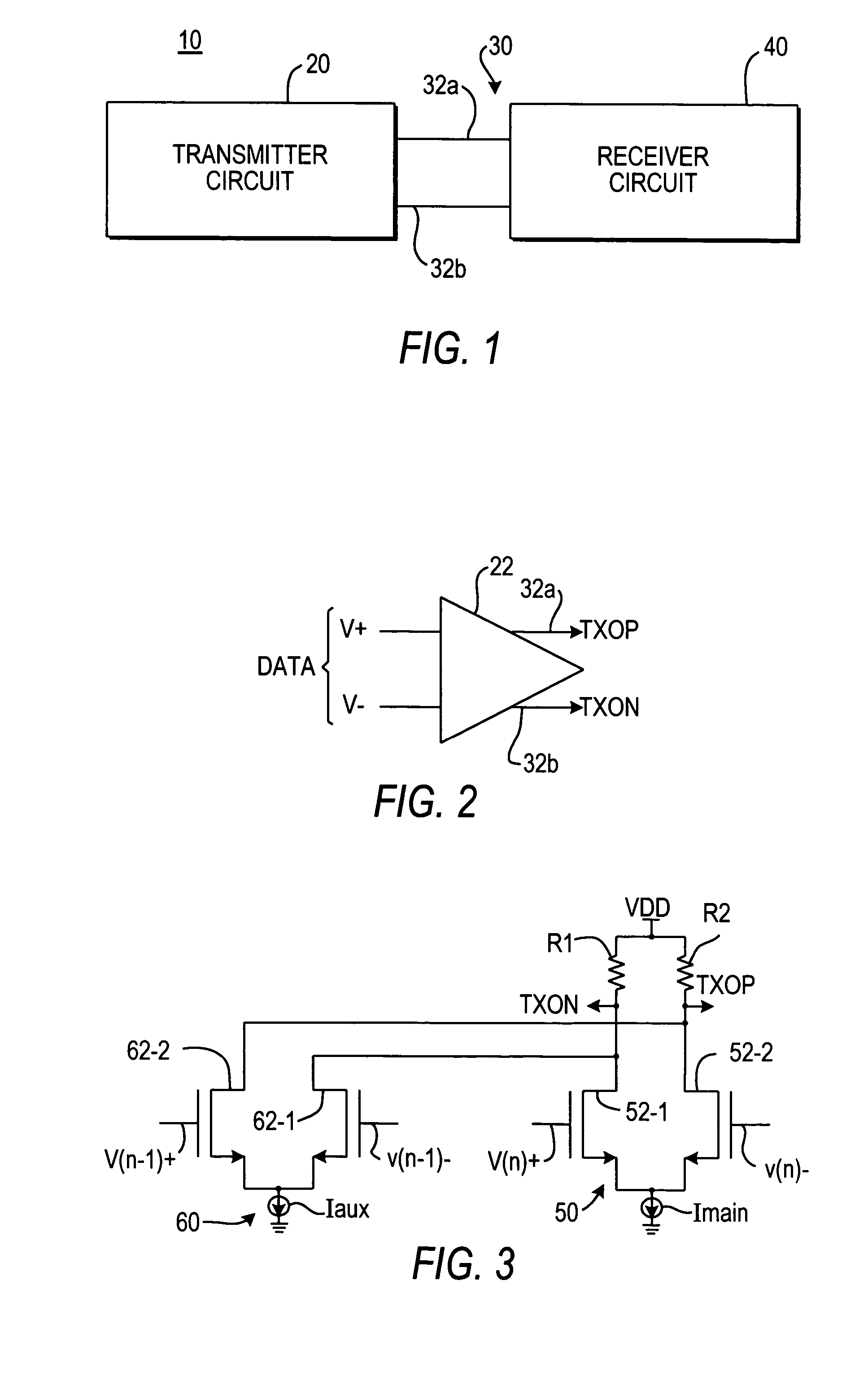
[0020]An illustrative system 10 employing digital signalling is shown in FIG. 1. System 10 includes transmitter circuit 20, receiver circuit 40, and a communication link 30 (including two conductors 32a and 32b) extending from circuit 20 to circuit 40. Communication link 30 is a differential signalling link, which means that different digital values are signalled by whether the voltage of the signal on lead 32a is higher than the voltage of the signal on lead 32b or vice versa. For example, digital value 1 may be represented by the voltage on conductor 32a being higher than the voltage on conductor 32b, and digital value 0 may be represented by the voltage on conductor 32b bein...


PUM


Abstract

Pre-emphasis is given to differential output signals emanating from a pair of output nodes by initially (after an input data signal transition) connecting at least two current circuits to only one of the nodes. After a time delay, one of the current circuits is switched to connect only to the node to which the current circuits were not previously connected if there has been no further transition in the input data signal during the time delay. If only single-ended (i.e., non-differential) output is desired, only one of the output nodes is used as an output signal source. More than two current circuits may be used, and their switching from one node to the other may be performed progressively to provide pre-emphasis having any of many different characteristics.

Description

BACKGROUND OF THE INVENTION[0001]This invention relates to circuitry for use in transmitters in differential or single-ended signalling circuitry or systems.[0002]In order to compensate for losses in the transmission of data signals—especially in digital systems operating at high speeds with low voltage signals—it may be desired to give the data signals what is called pre-emphasis. Pre-emphasis is extra power (usually extra voltage, but extra current may be an equivalent) immediately adjacent each transition in the level of the digital data signal. Pre-emphasis (provided by the circuitry transmitting the signal) helps to compensate for losses in transmission of the signal to receiver circuitry, and thereby helps the receiver circuitry respond more correctly to each transition in the transmitted signal.[0003]Known pre-emphasis circuitry (e.g., for low voltage differential signalling (“LVDS”)) may benefit from improvement, especially as systems attempt to use lower and lower power sup...

Claims


Application Information

Patent Timeline
Patent Type & Authority Patents(United States)
IPC IPC(8): H04L25/08H04L25/10H04L25/03H04L25/02
CPCH04L25/0288H04L25/0272
Inventor BAIG, MASHKOORWANG, SHOUJUNMEI, HAITAOBEREZA, BILLKWASNIEWSKI, TAD
Owner ALTERA CORP
Why Eureka
Try Eureka