Powerup control of PLL

a power-up control and pll technology, applied in pulse automatic control, oscillation generator, resonance circuit tuning, etc., can solve the problems of loop not operating properly, loops that cannot be phase locked, and the phase locked loop requires time to reach a locked sta

Active Publication Date: 2005-10-18
ANALOG DEVICES INC
View PDF8 Cites 20 Cited by
  • Summary
  • Abstract
  • Description
  • Claims
  • Application Information

AI Technical Summary

Benefits of technology

[0021]In another aspect, the invention comprises a method of operating a timing circuit having a phase locked loop. During a first interval, a check is made whether a control signal in the phase locked loop is between a maximum allowed value and a minimum allowed value. When the control signal in the phase locked loop is above a maximum allowed value or below a minimum allowed value, the phase locked loop is disabled for a second interval. When the control signal in the phase locked loop is below a maximum allowed value and above a minimum allowed value, indicating that the output of the phase locked loop is stable.

Problems solved by technology

However, when first turned on or when its operation is disrupted, a phase locked loop requires time to reach a locked state.
It is undesirable for the phase locked loop to run before the supply voltage exceeds an appropriate level.
However, if the appropriate power supply level is not supplied to the phase locked loop, the loop might not operate properly and might instead “lock” in an unintended operating state.

Method used


Image

  • Powerup control of PLL
  • Powerup control of PLL
  • Powerup control of PLL

Examples


Embodiment Construction

[0033]This invention is not limited in its application to the details of construction and the arrangement of components set forth in the following description or illustrated in the drawings. The invention is capable of other embodiments and of being practiced or of being carried out in various ways. Also, the phraseology and terminology used herein is for the purpose of description and should not be regarded as limiting. The use of “including,”“comprising,” or “having,”“containing”, “involving”, and variations thereof herein, is meant to encompass the items listed thereafter and equivalents thereof as well as additional items.

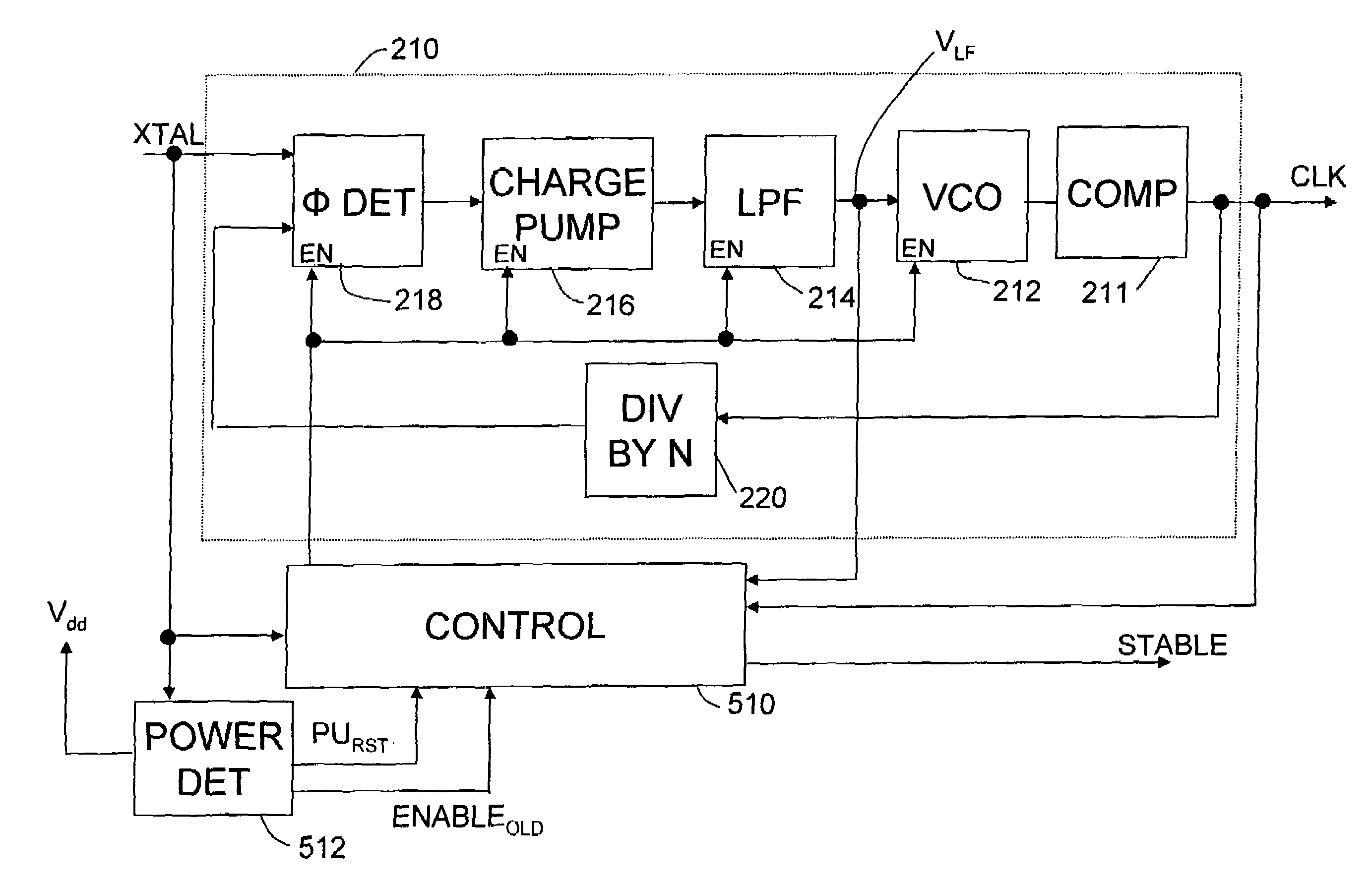
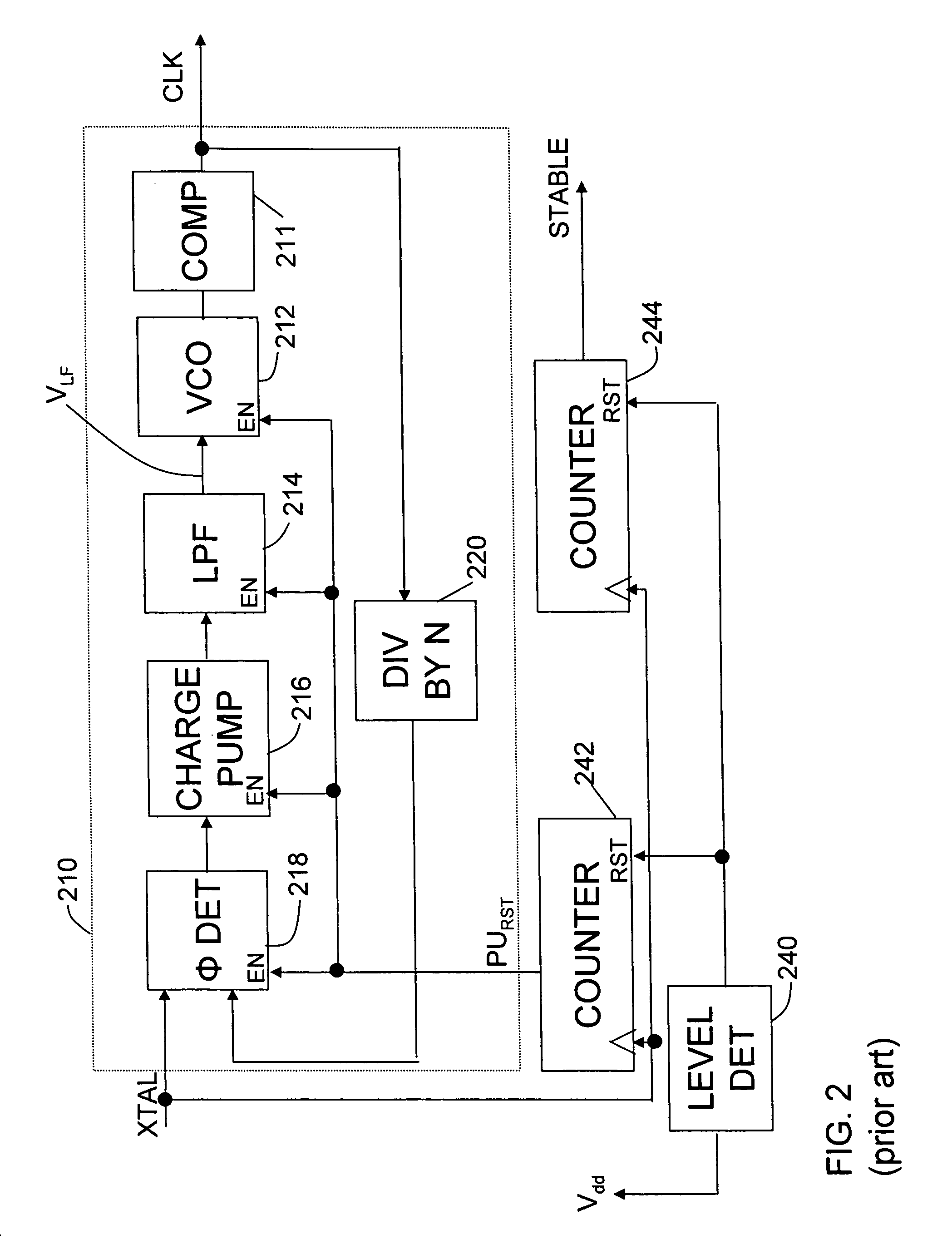
[0034]We have discovered that, despite circuitry to impose delays such as is shown in the timing circuit of FIG. 2, a timing circuit containing a phase locked loop might enter an unintended operating state. For example, process variations in CMOS devices might result in as much as a thirty-percent difference in operating characteristics from chip to chip. There...


PUM


Abstract

An electronic device, such as a microprocessor, with a timing circuit. The timing circuit contains a phase locked loop that, during a first interval, checks whether a control signal in the phase locked loop is between a maximum allowed value and a minimum allowed value. When the control signal in the phase locked loop is above a maximum allowed value or below a minimum allowed value, the control circuit disables the phase locked loop for a second interval. When the control signal in the phase locked loop is below a maximum allowed value and above a minimum allowed value, the timing circuit indicates that the output of the phase locked loop is stable.

Description

BACKGROUND OF INVENTION[0001]1. Field of Invention[0002]This invention relates generally to electronic devices and more specifically to clock or timing circuitry for use in such devices.[0003]2. Discussion of Related Art[0004]Computer data processors are widely used in modern electronic systems. For example, most desktop computers are built around a microprocessor chip. The microprocessor chip is a computer data processor that can be programmed to perform many data processing functions. Microprocessors perform arithmetic operations or logical operations that can be combined into many types of programs, such as those used to do accounting or word processing.[0005]Other computer data processors are designed for specialized functions. One example is a digital signal processor (DSP). A digital signal processor is kind of microprocessor that is configured to quickly perform complex mathematical operations used in processing digitized signals (e.g. audio or video signals).[0006]FIG. 1 sho...

Claims


Application Information

Patent Timeline
Patent Type & Authority Patents(United States)
IPC IPC(8): H03L7/06H03L3/00H03L7/095H03L7/10H03L7/18
CPCH03L3/00H03L7/095H03L7/10H03L7/18
Inventor WILSON, JAMESLAHR, LEWPATTERSON, STUARTBOYKO, DANIEL
Owner ANALOG DEVICES INC
Why Eureka
Try Eureka