Method and apparatus for pedestrian detection

a technology for pedestrian detection and detection methods, applied in scene recognition, television systems, instruments, etc., to achieve the effect of reducing damage or injury and avoiding pedestrians

Inactive Publication Date: 2005-10-18
SRI INTERNATIONAL +1
View PDF6 Cites 97 Cited by
  • Summary
  • Abstract
  • Description
  • Claims
  • Application Information

AI Technical Summary

Benefits of technology

[0008]The principles of the present invention provide for a pedestrian detection system that detects pedestrians proximate a vehicle. The system includes an optical sensor array comprised of stereo cameras that produce imagery that is processed to detect pedestrians. Such processing includes generating a plurality of disparity images at different resolutions. Those disparity images can be selectively used to produce depth maps (or depth image) of the scene proximate the vehicle by processing selected disparity images. The result is depth maps having different resolutions. The disparity images and / or the depth maps are processed and compared to pre-rendered templates of pedestrians. A list of possible pedestrians is subsequently produced by matching the pre-rendered templates to the disparity images and / or to the depth map. The system processes the possible pedestrian list to detect pedestrians near the vehicle. Pedestrian detection includes eliminating very eccentric peaks in a correlation image while retaining all peaks with an inverse eccentricity above a predetermined value, e.g. >0.4. Inverse eccentricity is the ratio of the minor and major axes of an ellipse corresponding to all nearby high correlation scores for the detected peaks. This information can be used in a number of ways, e.g., the pedestrians may be displayed to the driver, a warning may be given, or the information may be used in a pedestrian avoidance system that adjusts the trajectory or other parameters of the vehicle to safely avoid the pedestrian or mitigate damage or injury.

Problems solved by technology

Collision avoidance systems generally identify when an object is in front of a vehicle, but usually do not classify the object or provide any information regarding the movement of the object.

Method used


Image

  • Method and apparatus for pedestrian detection
  • Method and apparatus for pedestrian detection
  • Method and apparatus for pedestrian detection

Examples


Embodiment Construction

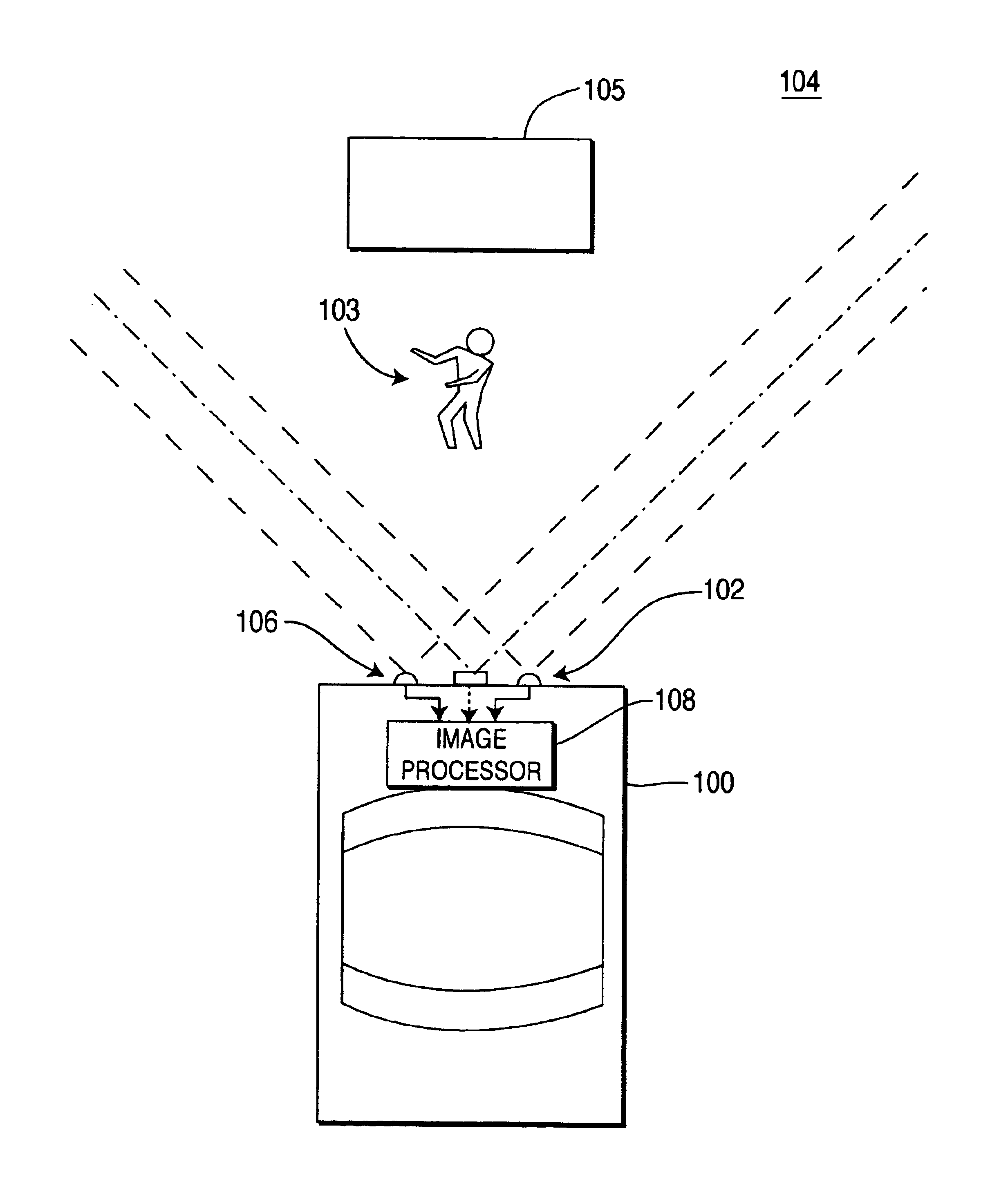
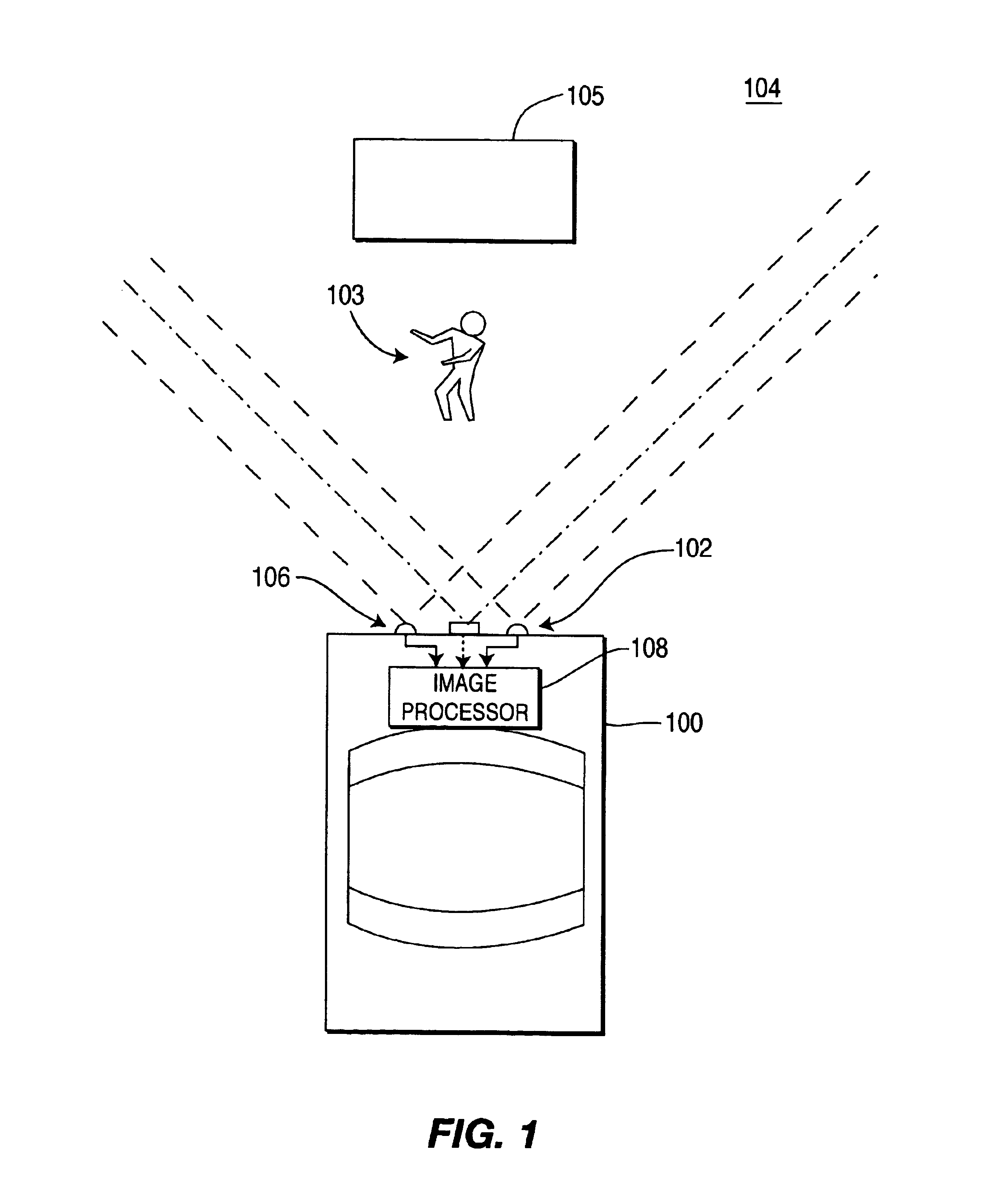
[0016]FIG. 1 depicts a schematic diagram of a vehicle 100 having a pedestrian detection system 102 that detects a pedestrian (or pedestrians) 103 within a scene 104 that is proximate the vehicle 100. That scene may include another object, such as a target vehicle 105. While in the illustrated embodiment the scene 104 is in front of the vehicle 100, other pedestrian detection systems may image scenes that are behind or to the side of the vehicle 100. Furthermore, the pedestrian detection system 102 need not be related to a vehicle, but can be used with any type of platform, such as a boat, a plane, an elevator, or even stationary streets, docks, or floors. The pedestrian detection system 102 comprises a sensor array 106 that is coupled to an image processor 108. The sensors within the sensor array 106 have a field of view that includes one or more pedestrians 103 and possibly one or more target vehicles 105.

[0017]The field of view in a practical pedestrian detection system 102 may be...


PUM


Abstract

A vehicle vision system that identifies pedestrians located proximate a vehicle. The system comprises a sensor array that produces imagery that is processed to generate disparity images. A depth map can be produced from the disparity images. Either the depth map or the disparity images are processed and compared to pedestrian templates. A pedestrian list is produced from the results of that comparison. The pedestrian list is processed to eliminate false pedestrians as determined by inverse eccentricity. The pedestrians are then tracked, and if a collision is possible, that information is provided to the driver and / or to an automated collision avoidance or damage or injury mitigation system.

Description

CROSS-REFERENCE TO RELATED APPLICATIONS[0001]This application claims the benefit of U.S. provisional patent application No. 60 / 484,464, filed Jul. 2, 2003, entitled, “Pedestrian Detection From Depth Images,” by Hirvonen, et al., which is herein incorporated by reference.[0002]This application is a continuation-in-part of pending U.S. patent application Ser. No. 10 / 461,699, filed on Jun. 13, 2003, entitled, “VEHICULAR VISION SYSTEM, by Camus et al. That patent application is hereby incorporated by reference in its entirety.BACKGROUND OF THE INVENTION[0003]1. Field of the Invention[0004]The present invention relates to artificial or computer vision systems, e.g. vehicular vision systems. In particular, this invention relates to a method and apparatus for detecting pedestrians in a manner that facilitates collision avoidance.[0005]2. Description of the Related Art[0006]Collision avoidance systems utilize a sensor system for detecting objects in front of an automobile or other form of v...

Claims


Application Information

Patent Timeline
Patent Type & Authority Patents(United States)
IPC IPC(8): B60Q1/00G06K9/00B60RG08G1/16
CPCG06K9/00201G06K9/00369G06K9/00805G06V20/64G06V40/103G06V20/58
Inventor HIRVONEN, DAVIDCAMUS, THEODORE ARMAND
Owner SRI INTERNATIONAL
Why Eureka
Try Eureka