
Phase change optical information recording medium

a phase change, optical information technology, applied in the direction of optical beam sources, recording signal processing, instruments, etc., can solve the problems of media incapable of recording or erasing information, discs become incapable of recording and reproducing information thereafter, and difficult control of recording and erasing, etc., to achieve the effect of easy control

Inactive Publication Date: 2005-10-18
RICOH KK
View PDF25 Cites 6 Cited by
  • Summary
  • Abstract
  • Description
  • Claims
  • Application Information

AI Technical Summary

Benefits of technology

[0031]Accordingly, an object of the present invention is to provide a rewritable phase change optical information recording medium in which information is recorded and erased while the recording and erasing are easily controlled (i.e., write protection is easily performed).
[0033]Yet another object of the present invention is to provide an information recording (and reproducing) method and apparatus in which information is recorded and erased while recording and erasing are easily controlled (i.e., while write-protection is easily performed).
[0035]A still further object of the present invention is to provide an information erasing method by which information recorded in a hybrid disc is securely erased.

Problems solved by technology

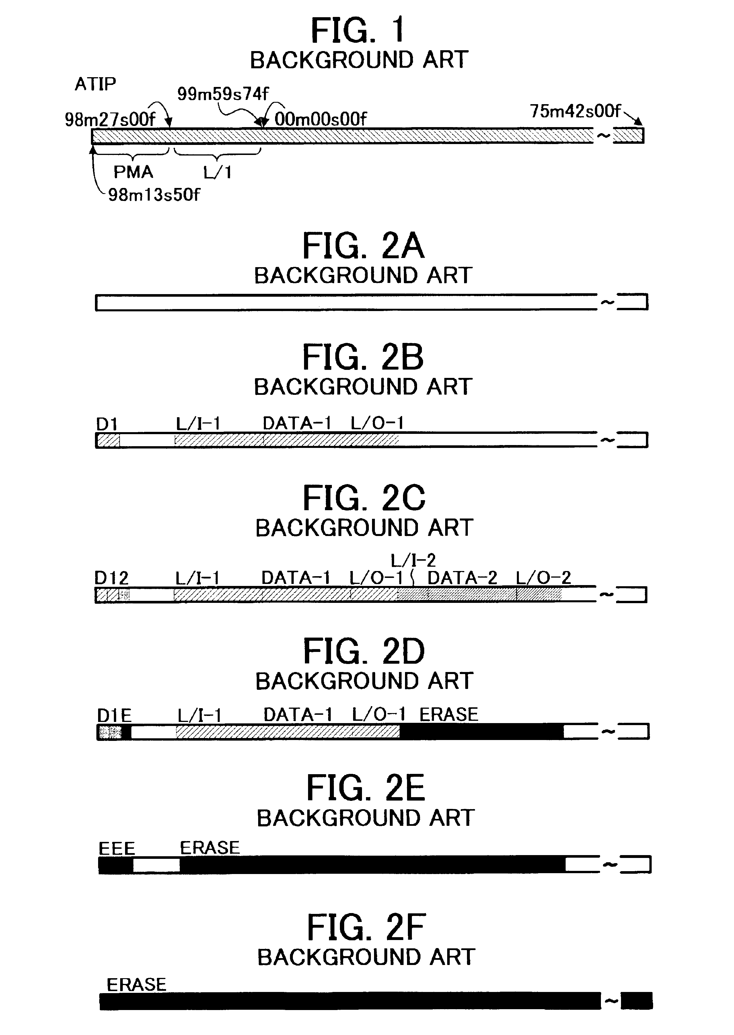
In this case, since the signals recorded in the first session and the ROM signals in the PMA are not erased and erasure signals are recorded therein, the disc becomes incapable of recording and reproducing information thereafter.
Thus, these media have drawbacks in that controlling of recording and erasing is difficult, and erasure signals are recorded in the ROM region by mistake, thereby making the media incapable of recording or erasing information.
Therefore the direct overwriting is performed while applying an excessive erasure power and thereby the recording layer tends to achieve an amorphous state, resulting in decrease of the land level.
Therefore, problems such that jitter increases and durability of the recording layer deteriorates occur.
In contrast, when the writing power (Pw) is relatively low compared to the optimum value thereof, the erasure power (Pe) also lowers, and thereby the previously recorded signals cannot be fully erased.
Therefore, a problem in that jitter increases occurs.
However, the optimum erasure power (Peo), which is changed by the OPC (optimization of the writing power) while depending on the optimum writing power (Pwo) which is determined according to the γ method described in the Orange Book, is not proper for the CW erasure power (Pecw).
Specifically, the portion on which the CW erasure is performed has deteriorated direct overwriting properties.
When logical erasure is performed on the hybrid discs, direct overwriting is performed on the ROM region thereof, and thereby the hybrid discs become incapable of reproducing information.

Method used


Image

  • Phase change optical information recording medium
  • Phase change optical information recording medium
  • Phase change optical information recording medium

Examples


example 1

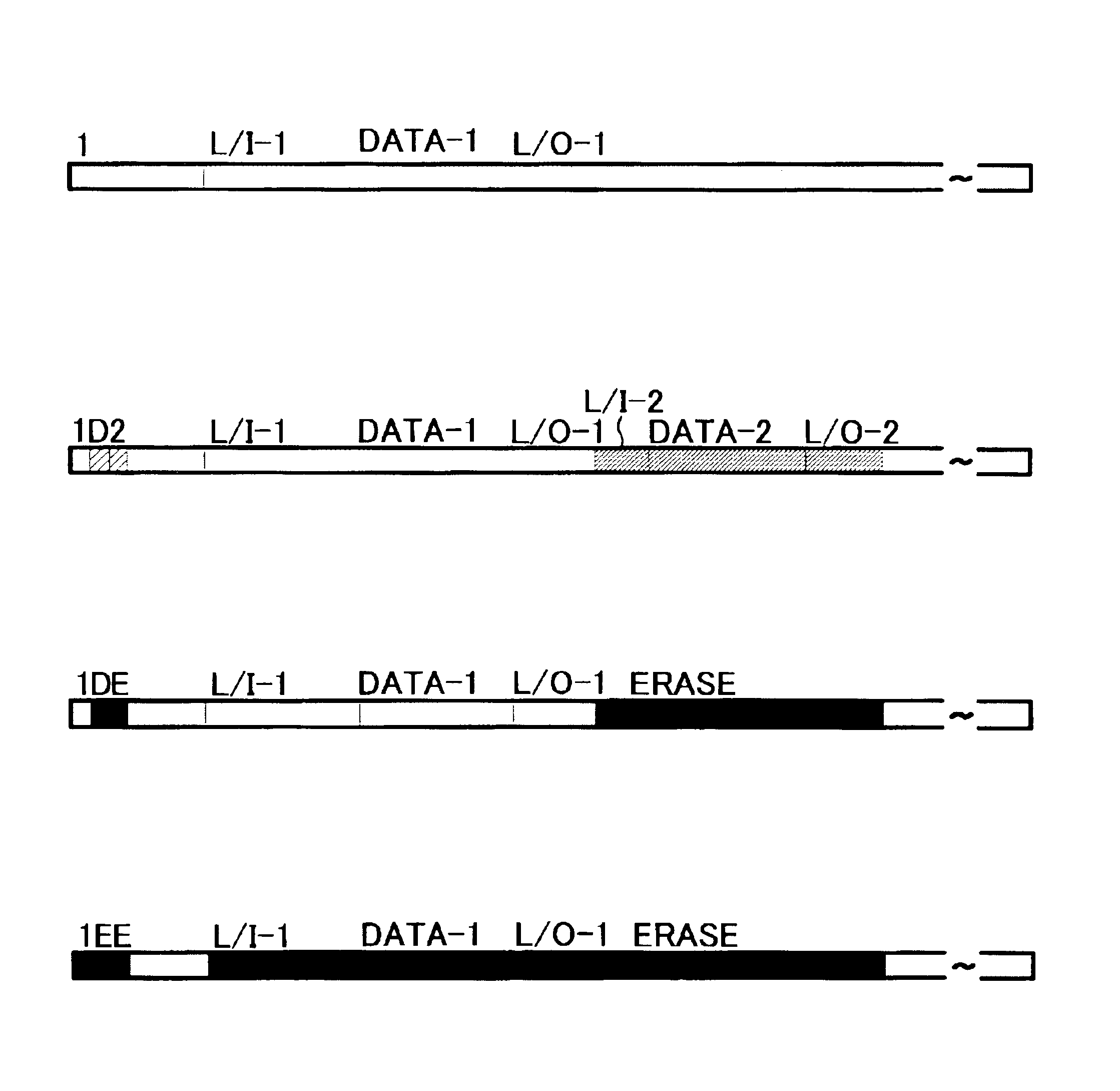
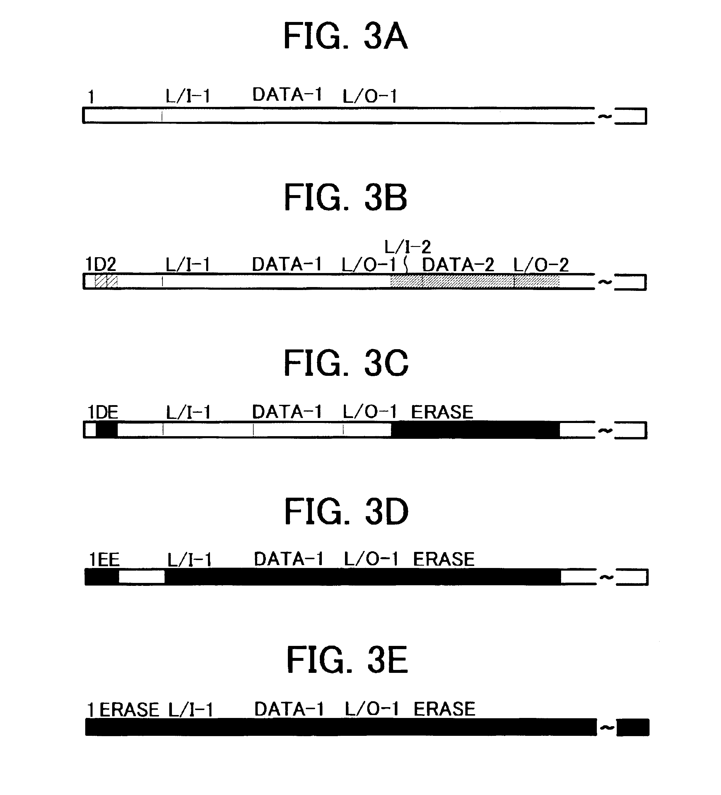
[0148]FIGS. 3A-3E are schematic views illustrating arrangement of information in the CD-RW having a ROM portion of the present invention.

[0149]FIG. 3A is a schematic view illustrating the CD-RW in a blank state. The following information has been recorded therein by pits.[0150](1) the position information of the first session located in an area of from 98m13s50f to 98m13s59f;[0151](2) the lead-in (L / I) area of the first session located in the area of from 98m27s00f to 99m59s74f;[0152](3) the data (Data) area of the first session located in the area of from 00m00s00f to 04m59s74f; and[0153](4) the lead-out (L / O) area of the first session located in the area of from 05m00s00f to 06m29s74f.

[0154]In the CD-RW as illustrated in FIG. 3B, the following information of the second session is additionally recorded:[0155](1) the disc ID information located in the area of from 98m13s50f to 98m13s69f;[0156](2) the position information of the second session in the area located in the area of from ...

example 2

[0191]A phase change optical information recording medium of the present invention was prepared. The recording medium includes a PMA of the first session at a position of 98m13s50f, which has a wobble signal; a L / I area of the first session at a position ranging from 98m27s00f to 99m59s74f, which has a wobble signal as illustrated in FIG. 9; a Data area of the first session at a position ranging from 00m00s00f to 04m59s74f, which does not have a wobble signal as illustrated in FIG. 6; and a L / O area of the first session at a position ranging from 05m00s00f to 06m29s74f, which has a wobble signal as illustrated in FIG. 9. The PMA and L / I, Data and L / O areas are formed of pits. In other areas, a guide groove having a wobble signal is formed on a substrate. Thus, a CD-RW including ATIP information was prepared.

[0192]As mentioned above, at least the first session including pits is formed on the substrate. Namely, the first session includes a ROM area which does not include a wobble sign...


PUM

PropertyMeasurementUnit
depthaaaaaaaaaa
widthaaaaaaaaaa
depthaaaaaaaaaa

Abstract

A phase change optical information recording medium including: a substrate; and a recording layer which is located overlying the substrate and in which marks are to be formed to store information, wherein the substrate includes plural sessions including a first session in which pits are formed and which includes a RAM region including a groove and a wobble signal, and a program memory area in which pits are formed and which includes position information of the first session and does not include disc ID information of the phase change optical information recording medium.

Description

BACKGROUND OF THE INVENTION[0001]1. Field of the Invention[0002]The present invention relates to an optical information recording medium, and particularly to a rewritable phase-change optical information recording medium for use as a CD-RW, DVD−RW, DVD+RW, etc. In addition, the present invention relates to a recording method and apparatus in which information is recorded in the optical information recording medium. Further, the present invention relates to an information recording method in which information is overwritten in the optical information recording medium. Furthermore, the present invention relates to an information erasing method.[0003]2. Discussion of the Related Art[0004]Conventional CD-RWs include a guide groove. As illustrated in FIG. 8, the guide groove is wobbled because wobble signals are recorded on entire the surface thereof in an irradiation process in stamping.[0005]The wobble signals include time (address) information called ATIP (absolute time in pre-groove)...

Claims


Application Information

Patent Timeline
Patent Type & Authority Patents(United States)
IPC IPC(8): G11B7/243G11B19/04G11B7/24G11B7/007G11B7/125G11B7/1267G11B7/24082
CPCG11B7/00557G11B7/006G11B7/00736G11B7/0079G11B7/1267G11B7/243G11B19/04G11B7/24082G11B2007/24308G11B2007/2431G11B2007/24314G11B2007/24316
Inventor NODA, EIJI
Owner RICOH KK
Learn More