Method and apparatus for reducing laser speckle using polarization averaging

a laser and speckle technology, applied in the direction of laser details, instruments, optical resonator shape and construction, etc., can solve the problems of exacerbated difficulty, destructive interference creates dark spots between bright spots, and speckle is a considerable problem, so as to reduce speckle, reduce speckle, reduce speckle

Inactive Publication Date: 2005-10-18
SILICON LIGHT MACHINES CORP
View PDF726 Cites 94 Cited by
  • Summary
  • Abstract
  • Description
  • Claims
  • Application Information

AI Technical Summary

Benefits of technology

[0012]The present invention is a method and apparatus for reducing speckle using polarization averaging. A polarizing beam splitter is configured to split a first polarized laser output into a second polarized laser output and a third polarized laser output. A plurality of mirrors creates an optical path difference between the second polarized laser output and the third polarized laser output. The optical path difference is at least about a coherence length of the first polarized laser output. The second polarized laser output and the third polarized laser output are combined into a fourth laser output. The fourth laser output illuminates a depolarizing screen. If an optical system having an intensity detector or an eye views the depolarizing screen, the intensity detector or the eye will detect reduced speckle. The reduced speckle is due to an averaging effect caused by uncorrelated speckle patterns created by the second polarized laser output and the third polarized laser output.

Problems solved by technology

Destructive interference creates dark spots between the bright spots.
Speckle is a considerable problem in many laser illuminated systems.
This difficulty is exacerbated by a relatively slow reduction in the contrast due to the 1 / √{square root over (N)} reduction factor.

Method used


Image

  • Method and apparatus for reducing laser speckle using polarization averaging
  • Method and apparatus for reducing laser speckle using polarization averaging
  • Method and apparatus for reducing laser speckle using polarization averaging

Examples


embodiment 37

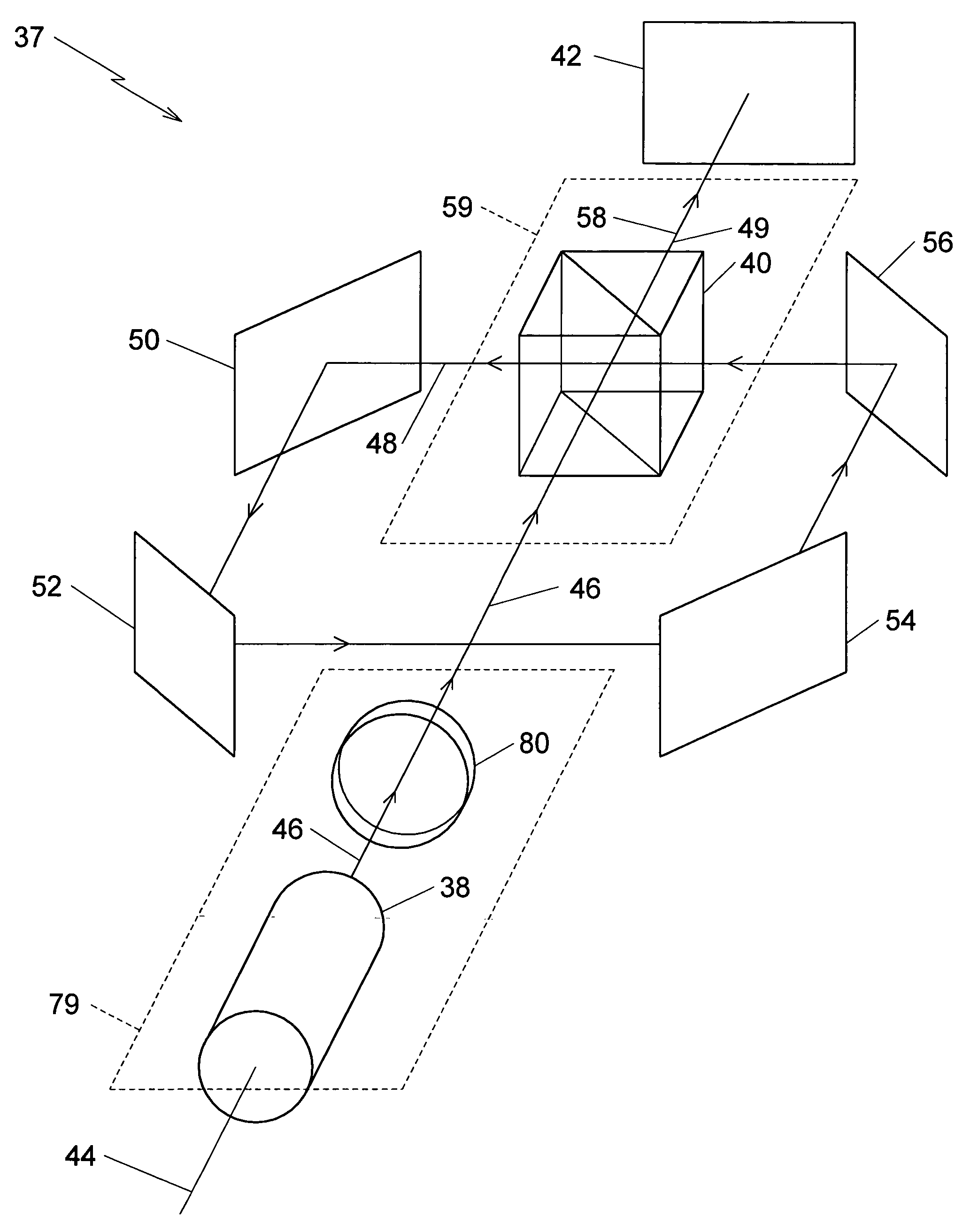
[0042]A plan view of the preferred embodiment 37 is illustrated in FIG. 7, including the polarizing beam splitter 40 and the first, second, third, and fourth mirrors 50, 52, 54, and 56, which are defined as a speckle reducing arrangement 68. The polarizing beam splitter 40 divides the first polarized laser output 46 into the second polarized laser output 48 and the third polarized laser output 49. The second polarized laser output 48 travels a first optical path length 70 from the polarizing beam splitting reflector 66 to the first mirror 50. The second polarized laser output 48 travels a second optical path length 72 from the first mirror 50 to the second mirror 52. The second polarized laser output 48 travels a third optical path length 74 from the second mirror 52 to the third mirror 54. The second polarized laser output 48 travels a fourth optical path length 76 from the third mirror 54 to the fourth mirror 56. The second polarized laser output 48 travels a fifth optical path le...

embodiment 84

[0047]A first alternative embodiment of the present invention is illustrated in FIG. 8. The first alternative embodiment 84 includes a fifth mirror 85, a sixth mirror 86, and a seventh mirror 88. The fifth, sixth, and seventh mirrors, 85, 86, and 88, form the light guide, which provides the optical path difference for the second polarized laser output 48.

embodiment 90

[0048]A second alternative embodiment of the present invention is illustrated in FIG. 9. The second alternative embodiment 90 includes a polarization preserving fiber optic 92, which forms the light guide providing the optical path difference for the second polarized laser output 48.


PUM


Abstract

A method and apparatus for reducing speckle uses polarization averaging. A polarizing beam splitter divides a first polarized laser output into a second polarized laser output and a third polarized laser output. A plurality of mirrors creates an optical path difference between the second and third polarized laser outputs. The optical path difference is at least about a coherence length for the first polarized laser output. The second and third polarized laser outputs are combined into a fourth laser output, which illuminates a depolarizing screen. If a human eye or an optical system having a intensity detector views the depolarizing screen, the eye or the intensity detector will detect reduced speckle, which results from uncorrelated speckle patterns created by the second polarized laser output and the third polarized laser output. A first alternative embodiment of the invention functions without the optical path difference being at least about the coherence length. In the first alternative embodiment, a piezoelectric transducer varies an optical path length by at least about a half wavelength of the first polarized laser output. By varying the optical path length by a sufficient frequency, the eye or the intensity detector will detect the reduced speckle. A second alternative embodiment combines two orthogonally polarized laser outputs, from two lasers, into a combined laser output. The combined laser output illuminates the depolarizing screen. A third alternative embodiment rotates the first laser output with a rotation frequency to form a rotating polarized laser output, which illuminates the depolarizing screen.

Description

FIELD OF THE INVENTION[0001]The present invention relates to the field of coherently illuminated systems. More particularly, the present invention relates to the field of reducing speckle in laser illuminated systems.BACKGROUND OF THE INVENTION[0002]Coherent light illuminating a rough surface produces speckle. Reflection from the rough surface is referred to as diffuse reflection. Transmission through the rough surface is referred to as diffuse transmission. In the diffuse reflection or the diffuse transmission, light scatters in various directions. The coherent light scattered by the diffuse reflection or by the diffuse transmission forms an interference pattern in the space away from the rough surface. If viewed by a human eye, the eye will see dark and light in a ‘granular’ pattern. The granular pattern is the speckle. An intensity detector of an optical system will also detect the speckle if the optical system views the rough surface illuminated by the coherent light.[0003]A fir...

Claims


Application Information

Patent Timeline
Patent Type & Authority Patents(United States)
IPC IPC(8): G02B27/48G02B27/28
CPCG02B27/48
Inventor TRISNADI, JAHJA I.
Owner SILICON LIGHT MACHINES CORP
Why Eureka
Try Eureka