Vertical small angle x-ray scattering system

a small angle x-ray scattering and vertical technology, applied in the field of xray scattering analysis, can solve the problems of relatively difficult loading and manipulating samples within the system, and liquid samples are typically not homogeneous in thickness, and achieve the effect of reducing distan

Inactive Publication Date: 2005-10-18
BRUKER AXS
View PDF17 Cites 13 Cited by
  • Summary
  • Abstract
  • Description
  • Claims
  • Application Information

AI Technical Summary

Benefits of technology

[0006]The front portion of the system, including the x-ray source, may be located in a primary beampath that is isolated from an external environment. This primary beampath leads to a sample chamber in which the sample support is located. The sample chamber may itself be isolated from the external environment, and may be provided with at least one access port that provides access to the sample from the outside. In addition, the primary beampath may be evacuated, and the primary beampath and sample chamber separated by a diaphragm that creates a fluid seal to maintain the vacuum. The back end of the system, including the detector, may be located in a secondary beampath that is also isolated from the external environment. As with the primary beampath, the secondary beampath may be evacuated, and may be separated from the sample chamber by a diaphragm. The secondary beampath may also extend into the sample chamber to minimize the distance that the scattered x-ray energy must travel through the unevacuated space of the sample chamber.

Problems solved by technology

Although the horizontal systems make it relatively simple to access system components, they suffer from several drawbacks.
However, when stored in such capillaries, the liquid samples are typically not homogeneous in thickness in directions parallel to the x-ray beam direction.
Moreover, a significant amount of container surface area is encountered by the source x-ray beam, resulting in additional unwanted scattering signals, and the samples are relatively difficult to load and manipulate within the system.

Method used


Image

  • Vertical small angle x-ray scattering system
  • Vertical small angle x-ray scattering system
  • Vertical small angle x-ray scattering system

Examples


Embodiment Construction

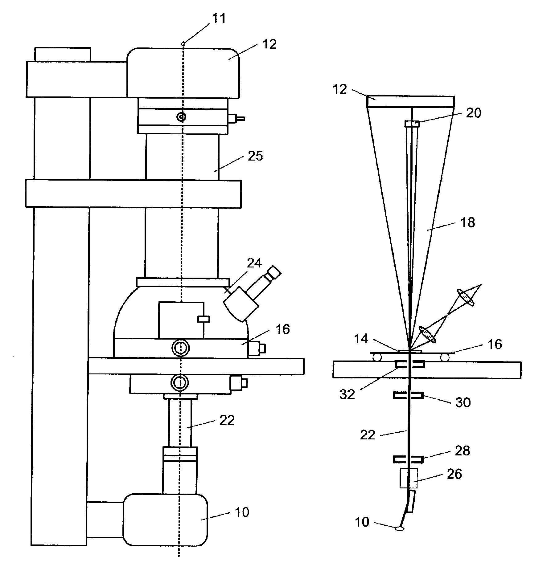
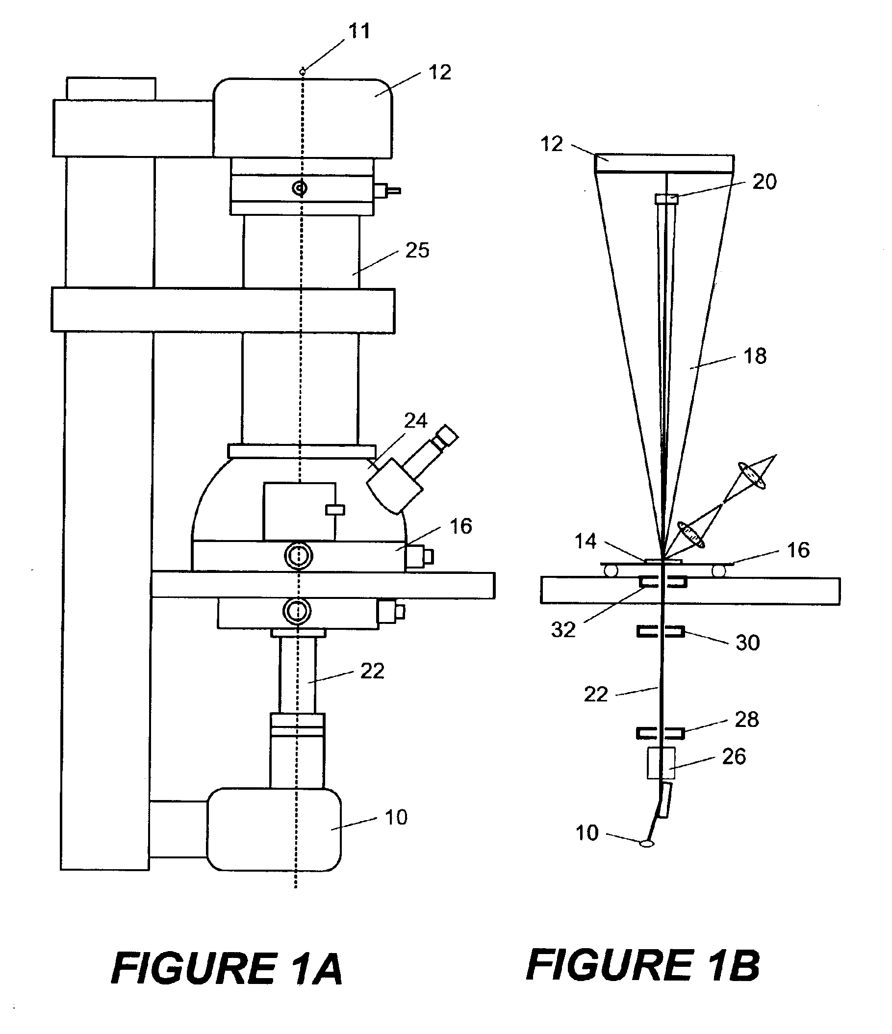
[0014]Shown in FIG. 1A is a front view of a small angle x-ray scattering analysis system according to the present invention. FIG. 1B shows a more schematic arrangement of the interior components of this system for sake of clarity. The same reference numerals are used, respectively, in each of the two figures to indicate common components and thereby allow correspondence between them. As shown, the system is oriented with the x-ray transmission axis 11 in a vertical orientation with an x-ray source 10 located at the bottom and an x-ray detector 12 at the top. Those skilled in the art will recognize that an alternative configuration could also be used in which the x-ray source 10 was located at the top and the detector at the bottom, while still maintaining the system in a vertical configuration.

[0015]The source 10 is a conventional x-ray source for use with small-angle scattering systems, such as a sealed x-ray tube or a rotating anode generator, with spot focus being preferred. As a...


PUM

PropertyMeasurementUnit
anglesaaaaaaaaaa
diameteraaaaaaaaaa
pixel sizeaaaaaaaaaa

Abstract

A small angle x-ray diffraction scattering system has a vertical orientation, allowing for simplified analysis of liquid samples. The system may function in a beam-up or a beam-down configuration. An x-ray source provides an initial x-ray beam that is directed vertically along a primary beampath to a sample located on a sample support. The small angle scattered x-ray energy travels through a secondary beampath to a detector. The primary and secondary beampaths may be evacuated and separated from a sample chamber by fluid seals. Beam conditioning optics and a collimator may be used in the primary beampath, and a beamstop used in the secondary beampath. The sample chamber may have a microscope or camera, which may be movable, for observing the sample, and a translation stage for moving the sample in at least two dimensions.

Description

FIELD OF THE INVENTION[0001]This invention relates generally to the field of x-ray scattering analysis and, more specifically, to small angle x-ray scattering analysis systems.BACKGROUND OF THE INVENTION[0002]Small angle x-ray scattering is a specialized area within the more general field of x-ray scattering analysis. Unlike the more general wide-angle scattering systems, small angle systems measure phenomena that are observed within angles of just a few degrees from the primary x-ray beam. Thus, such systems may be used to provide structural information on the order of approximately one to one hundred nanometers. This allows characterization of a variety of materials that are not measurable using a wide angle system. However, small angle systems must also face a number of additional problems due to the small angle measurements.[0003]In a small angle x-ray scattering system, the distance between the sample being examined and the x-ray detector is typically much longer than that of a...

Claims


Application Information

Patent Timeline
Patent Type & Authority Patents(United States)
IPC IPC(8): G01N23/20G01N23/201
CPCG01N23/201G01N23/207
Inventor HE, BOB BAOPINGSCHIPPER, ROLF DIETER
Owner BRUKER AXS
Why Eureka
Try Eureka