Dynamic current-to-pneumatic converter and pneumatic amplifier

a current-to-pneumatic converter and amplifier technology, applied in the field of valve position systems, can solve the problems of difficult manufacturing and lack of consistent dynamic response, and achieve the effect of reliable steady-state amplifier performan

Inactive Publication Date: 2005-10-18
DRESSER IND INC
View PDF46 Cites 24 Cited by
  • Summary
  • Abstract
  • Description
  • Claims
  • Application Information

AI Technical Summary

Benefits of technology

[0008]A dynamically balanced pneumatic relay is disclosed. In one example, the relay has a balance plug, a supply plug positioned on top of the balance plug, a bead chain connecting the balance plug and the supply plug, and a vent plug positioned on top of the supply plug. The relay integrated with the balance plug, the supply plug, and the vent plug avoids a flow deadband during which a signal pressure generated by the amplifier ...

Problems solved by technology

The spool valve provides a very consistent dynamic response, but is difficult to manufacture to ensure that it performs well in a steady state.
The tr...

Method used


Image

  • Dynamic current-to-pneumatic converter and pneumatic amplifier
  • Dynamic current-to-pneumatic converter and pneumatic amplifier
  • Dynamic current-to-pneumatic converter and pneumatic amplifier

Examples


Embodiment Construction

[0018]This application incorporates by reference in its entirety U.S. Pat. No. 6,272,401 of which this application is a Continuation-in-Part.

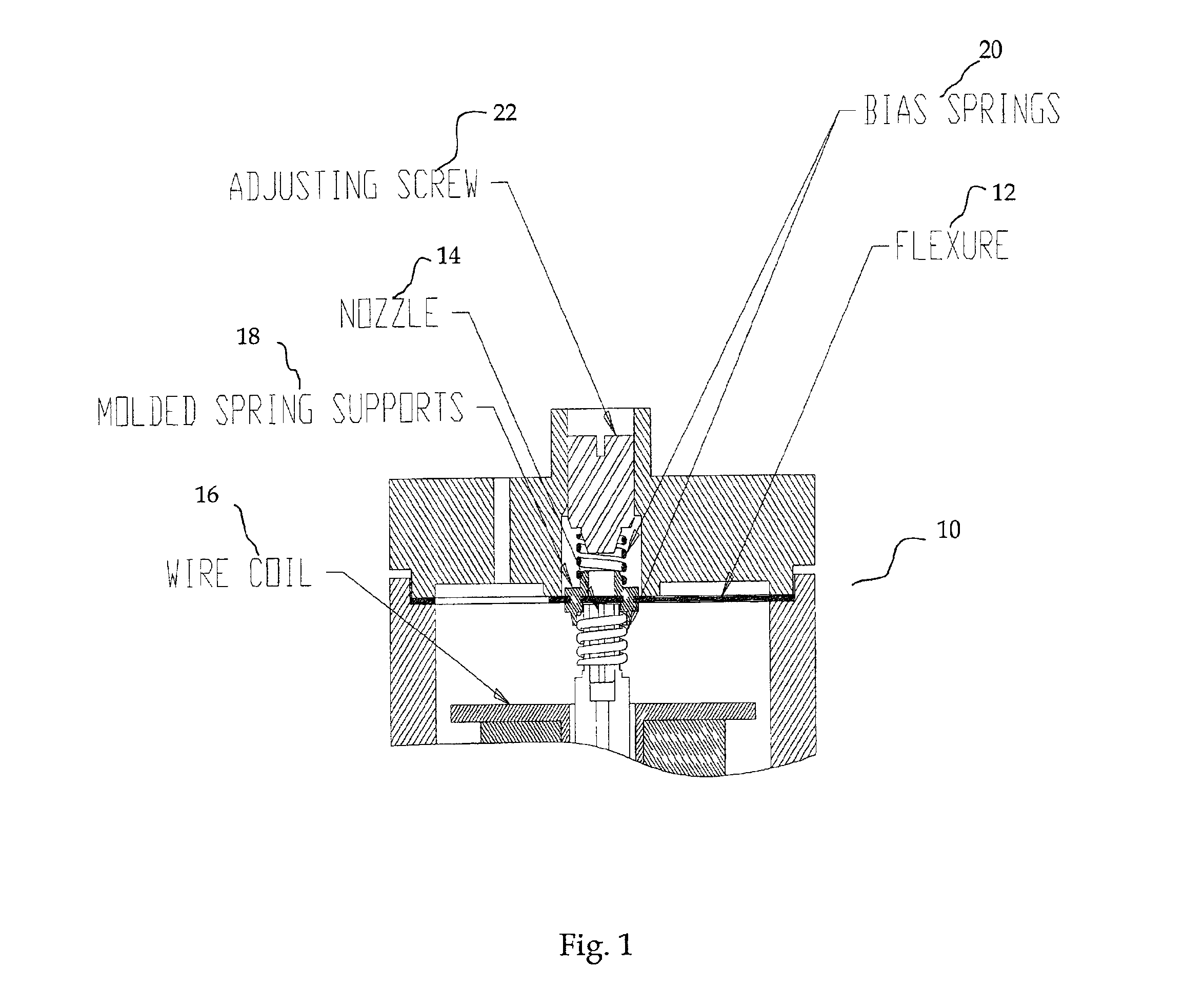
[0019]Referring to FIG. 1, a portion of an I / P converter 10 is shown. As described above, the purpose of the I / P converter is to generate a signal pressure proportional to a given electrical current. One improved design of a low cost I / P converter according to one example of the present invention uses a flexure-nozzle arrangement to produce the signal pressure. A flexure 12 is a flat strip located in close proximity to a nozzle 14. The flexure 12 is acted on by a variable magnetic force produced by a current flowing through a wire coil 16, thereby creating a back pressure in the nozzle. The flexure is further integrated with a molded spring support 18 and two bias springs 20. There is an adjusting screw 22 sitting on top of the I / P converter.

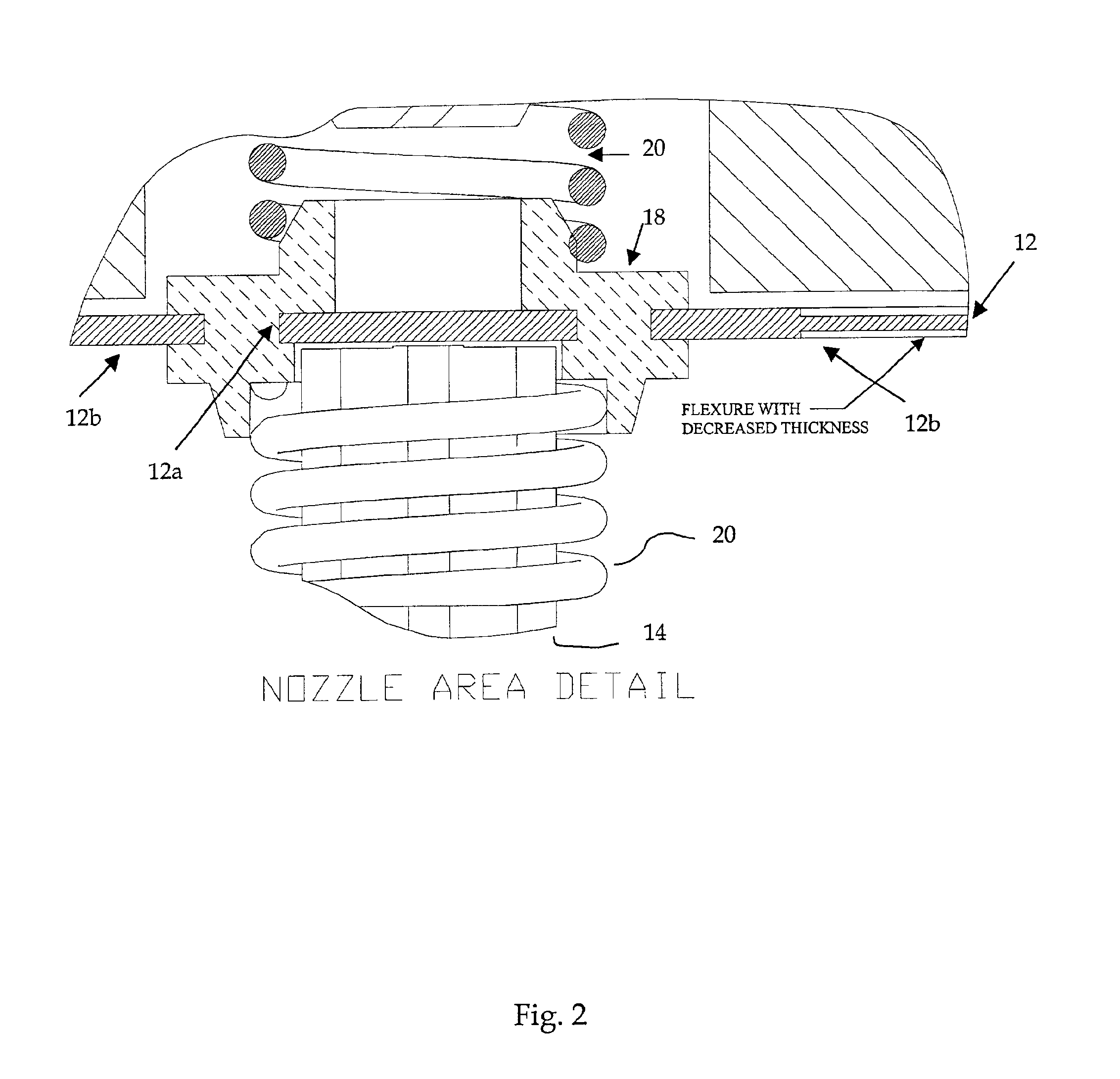
[0020]Referring now to FIG. 2, a detailed view of a flexure assembly is shown. As it is clearly shown, t...


PUM


Abstract

A dynamically balanced pneumatic relay amplifier and a current-to-pneumatic converter are disclosed. The relay has a balance plug, a supply plug positioned on top of the balance plug, a bead chain connecting the balance plug and the supply plug, and a vent plug positioned on top of the supply plug. The relay also includes a baffle positioned on top of the vent plug. The converter, used in an electro-pneumatic positioner, comprises a flat strip made of magnetic material located in proximity to a nozzle, and a flow regulator having a flat spring securing a plug in a seat within the regulator. The converter also includes a cantilevered flexure integrally secured to a molded spring support, a first bias spring positioned on a first side of the flexure, and a second bias spring positioned on a second side of the flexure. The thickness of the flexure is locally reduced in an area not integrated into the molded spring support.

Description

CROSS REFERENCE[0001]This application is a Continuation-in-Part application of Ser. No. 09 / 118,406, filed Jul. 17, 1998, now U.S. Pat. No. 6,272,401 which issued on Aug. 7, 2001 and claims benefit of provisional application 60 / 053,648 Jul. 23, 1997BACKGROUND OF THE INVENTION[0002]The present invention relates generally to valve position systems, and more particularly, to a flexure used in a current-to-pneumatic (I / P) converter, a low cost I / P converter, and a dynamically balanced pneumatic amplifier.[0003]One major purpose of an I / P converter is to produce a pneumatic pressure proportional to a given electrical current. This produced pressure may be referred to as a signal pressure. This signal pressure is traditionally amplified, both in pressure and volume, and fed to a pneumatic actuator used to position a valve in a valve positioner system as described in the U.S. patent application Ser. No. 09 / 118,406, which is assigned to the same assignee and incorporated herein by reference....

Claims


Application Information

Patent Timeline
IPC IPC(8): G05B7/02G05B11/42G05B19/00G05B7/00G05B5/00G05B5/01G05B19/44F15B5/00F15B19/00
CPCF15B5/006F15B19/005G05B5/01G05B7/02G05B11/42G05B19/44G05B2219/25252G05B2219/41032G05B2219/41143G05B2219/41154G05B2219/41304G05B2219/41311F15B21/087
Inventor SMART, HAROLD R.ZHOU, CHUHE
Owner DRESSER IND INC
Why Eureka
Try Eureka