System for controlling drivetrain components to achieve fuel efficiency goals

a technology of drivetrain components and fuel efficiency, applied in the direction of driver input parameters, external condition input parameters, special data processing applications, etc., can solve the problems of reducing the drivability of the vehicle, defeating the purpose of engine speed limit, etc., to achieve fuel efficiency, high-performance engine operation, and fuel-efficient engine operation.

Inactive Publication Date: 2005-10-18
CUMMINS INC
View PDF51 Cites 53 Cited by
  • Summary
  • Abstract
  • Description
  • Claims
  • Application Information

AI Technical Summary

Benefits of technology

[0020]One object of the present invention is to provide a system for controlling engine operation to thereby maximize fuel economy, particularly during transmission gear shifting operations.
[0021]Another object of the present invention is to provide a system for controlling shift points of a number of gears of a transmission to thereby achieve fuel efficient engine operation.
[0022]Still another object of the present invention is to provide a system for controlling shift points of a number of gears of a tra

Problems solved by technology

For example, under high engine load operating conditions, such as when traversing a grade and/or when hauling a heavily loaded trailer, providing a hard limit 10 on available engine speed can hinder the drivab

Method used


Image

  • System for controlling drivetrain components to achieve fuel efficiency goals
  • System for controlling drivetrain components to achieve fuel efficiency goals
  • System for controlling drivetrain components to achieve fuel efficiency goals

Examples


Embodiment Construction

[0073]For the purposes of promoting an understanding of the principles of the invention, reference will now be made to the embodiments illustrated in the drawings and specific language will be used to describe the same. It will nevertheless be understood that no limitation of the scope of the invention is thereby intended, such alterations and further modifications in the illustrated devices, and such further applications of the principles of the invention as illustrated therein being contemplated as would normally occur to one skilled in the art to which the invention relates.

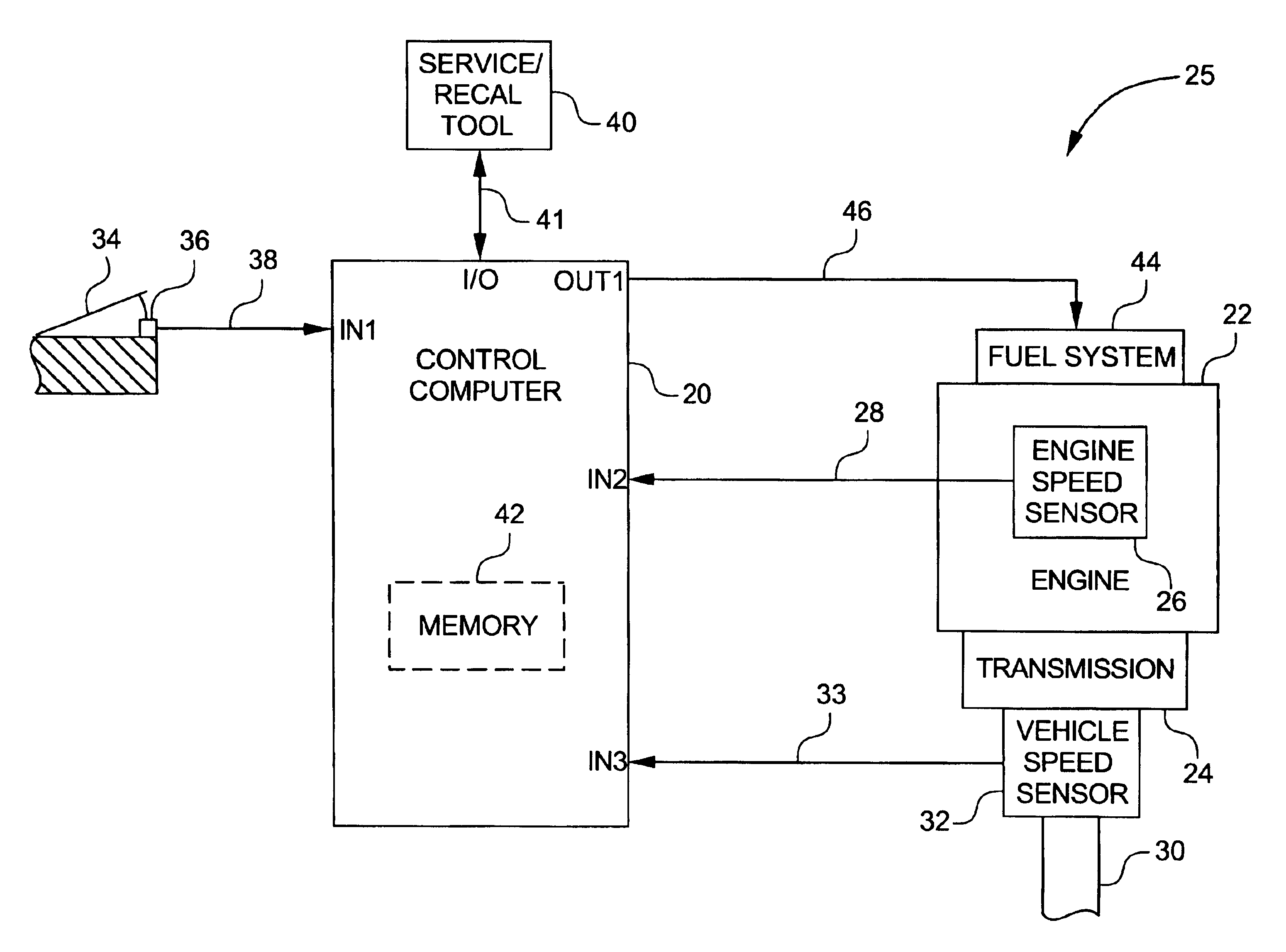
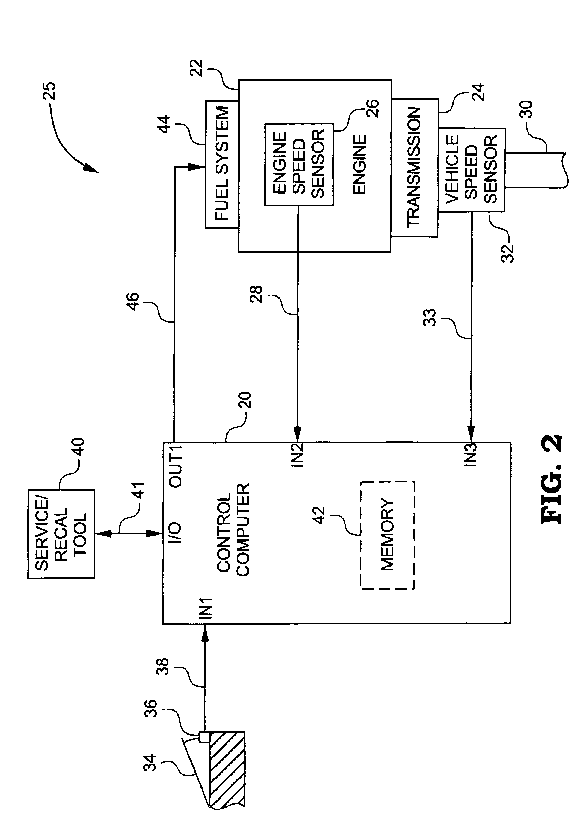
[0074]Referring now to FIG. 2, one preferred embodiment of a system 25 for controlling engine operation, in accordance with the present invention, is shown. Central to system 25 is a control computer 20 which interfaces with various engine and / or vehicle components as will be discussed more fully hereinafter. Control computer 20 is preferably microprocessor-based and includes at least a memory portion 42, digi...


PUM


Abstract

A system for controlling a vehicle drivetrain in a fuel-efficient manner includes a control computer operable to define a contour from substantially zero engine load to substantially full engine load, wherein the contour may correspond to a fuel-efficient path from no-load to full-load engine operating conditions. With change gear transmissions, the control computer is operable to control transmission shift points about the contour. With continuous variable transmissions the control computer is operable to modify the effective gear ratio thereof to maintain engine operation on or about the contour. In either case, fuel efficient operation may be optimized.

Description

CROSS-REFERENCE TO RELATED U.S. PATENT APPLICATION[0001]This is a divisional of U.S. application Ser. No. 10 / 080,049, filed Feb. 21, 2002, now U.S. Pat. No. 6,546,329, which is a divisional of U.S. application Ser. No. 09 / 616,752, filed Jul. now U.S. Pat. No. 6,436,005, which is a continution-in-part of U.S. Ser. No. 09 / 502,641, filed Feb. 11, 2000, now U.S. Pat. No. 6,387,011, which is a continution-in-part of U.S. Ser. No. 09 / 099,545, filed Jun. 18, 1998, now U.S. Pat. No. 6,042,505.FIELD OF THE INVENTION[0002]The present invention relates generally to systems for electronically controlling and managing the operation of drivetrain components including internal combustion engines and change gear transmissions, and more specifically to such systems for controlling such drivetrain components during gear shifting operations.BACKGROUND OF THE INVENTION[0003]Electronic control systems for managing the operation of internal combustion engines are well known and widely used in the automot...

Claims


Application Information

Patent Timeline
IPC IPC(8): F02D41/14F02D41/00F02D31/00F02D41/02F02D41/24F16H61/02F16H59/50F16H59/52F16H63/50F16H63/00B60K26/00B60W10/06B60W10/10B60W30/18B60W50/00F02D43/00F16H61/66G06F7/00G06G7/70
CPCB60W10/06B60W10/10B60W10/11B60W30/1882F02D31/009F02D41/0225F02D41/023F02D41/1497F02D41/2406F02D41/2422F16H61/0213F16H61/66B60K2741/045Y10T477/679B60K2741/145B60T2250/02B60W2050/0066B60W2510/0609B60W2510/0638B60W2510/1005B60W2510/105B60W2520/10B60W2530/10B60W2530/16B60W2540/04B60W2540/10B60W2540/30B60W2550/142B60W2550/16B60W2550/22B60W2550/402B60W2710/0644B60W2710/0677B60W2720/10B60W2720/106F02D2041/2048F02D2200/0404F02D2200/0614F02D2200/1002F02D2200/1004F02D2200/1012F02D2200/501F02D2200/602F02D2200/701F02D2200/702F02D2250/26F02D2400/12F16H59/52F16H63/50F16H2061/022Y02T10/52Y02T10/76F16H2061/0015F16H2059/663F16H2059/666Y10T477/675Y10T477/68B60K2741/065B60W10/04B60W10/101B60W30/1819Y02T10/84B60W2555/80B60W2540/215B60W2555/60B60W2556/50B60W2552/15Y02T10/40B60W2050/0042B60W50/082B60W50/085
Inventor BELLINGER, STEVEN M.
Owner CUMMINS INC
Why Eureka
Try Eureka