
Vibratory transducer

a transducer and vibration technology, applied in the field of vibration transducers, can solve the problems of composite case caps, which can be made at lower cost even in small numbers, often do not have the required pressure resistances, and unfavorable three-dimensional shapes, etc., to achieve mass increase, increase pressure resistance, increase pressure resistance

Inactive Publication Date: 2005-10-25
ENDRESSHAUSER FLOWTECH
View PDF7 Cites 17 Cited by
  • Summary
  • Abstract
  • Description
  • Claims
  • Application Information

AI Technical Summary

Benefits of technology

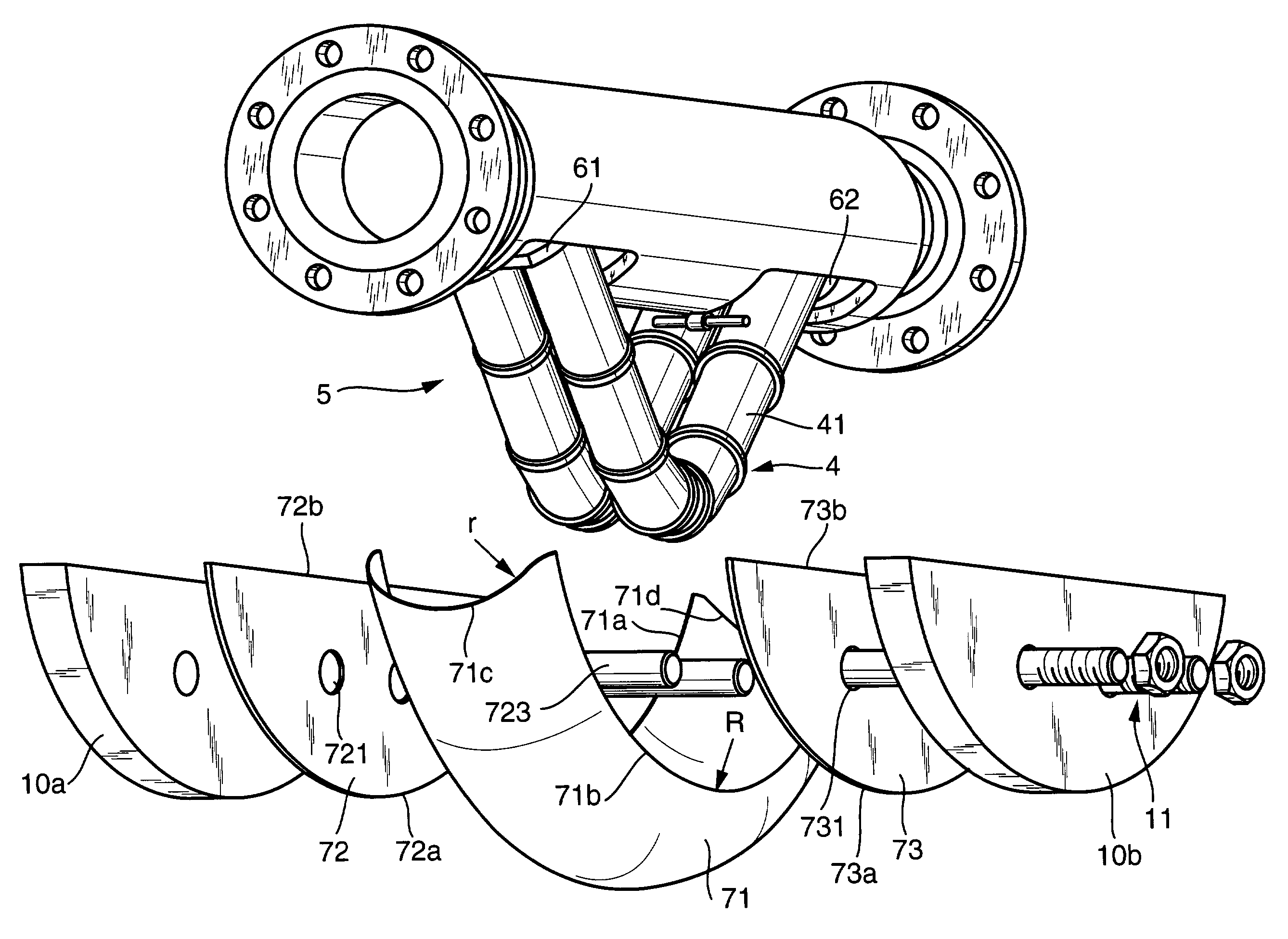
[0033]One advantage of the invention consists in the fact that because of the use of the channel-shaped and, hence, comparatively thin-walled cap segment and a rather slight mass increase as compared to, e.g., the case according to the above-mentioned European Patent Application EP 01 120 561.4, for instance through the use of additional stiffening and / or clamping elements in the areas of the two plane cap segments, a substantial increase in pressure resistance can be achieved. Investigations have shown that with a mass increase by about 20%, for instance through the use of side plates for the stiffening elements and of tension bolts for the clamping elements, and with virtually unchanged geometry, an increase in pressure resistance by more than 200% can be achieved.
consists in the fact that because of the use of the channel-shaped and, hence, comparatively thin-walled cap segment and a rather slight mass increase as compared to, e.g., the case according to the above-mentioned European Patent Application EP 01 120 561.4, for instance through the use of additional stiffening and / or clamping elements in the areas of the two plane cap segments, a substantial increase in pressure resistance can be achieved. Investigations have shown that with a mass increase by about 20%, for instance through the use of side plates for the stiffening elements and of tension bolts for the clamping elements, and with virtually unchanged geometry, an increase in pressure resistance by more than 200% can be achieved.

Problems solved by technology

While the required mechanical strength, particularly the required pressure resistance, can generally be readily provided by the support frame, particularly if the latter is in the form of a cylindrical tube, additional measures to increase the pressure resistance must be taken on the case caps because their three-dimensional shape is unfavorable for safety vessels.
While, as also stated in European Patent Application EP 01 120 561.4, case caps fabricated by deep drawing can be made economically only in large quantities because deep-drawing dies are very expensive, the composite case caps, which can be made at lower cost even in small numbers often do not have the required pressure resistances.

Method used


Image

  • Vibratory transducer
  • Vibratory transducer
  • Vibratory transducer

Examples


Embodiment Construction

[0039]While the invention is susceptible to various modifications and alternative forms, exemplary embodiments thereof have been shown by way of example in the drawings and will herein be described in detail. It should be understood, however, that there is no intent to limit the invention to the the particular forms diclosed, but on the contrary, the intention is to cover all modifications, equivalents, and alternatives falling within the spirit and scope of the invention as defined by the intended claims.

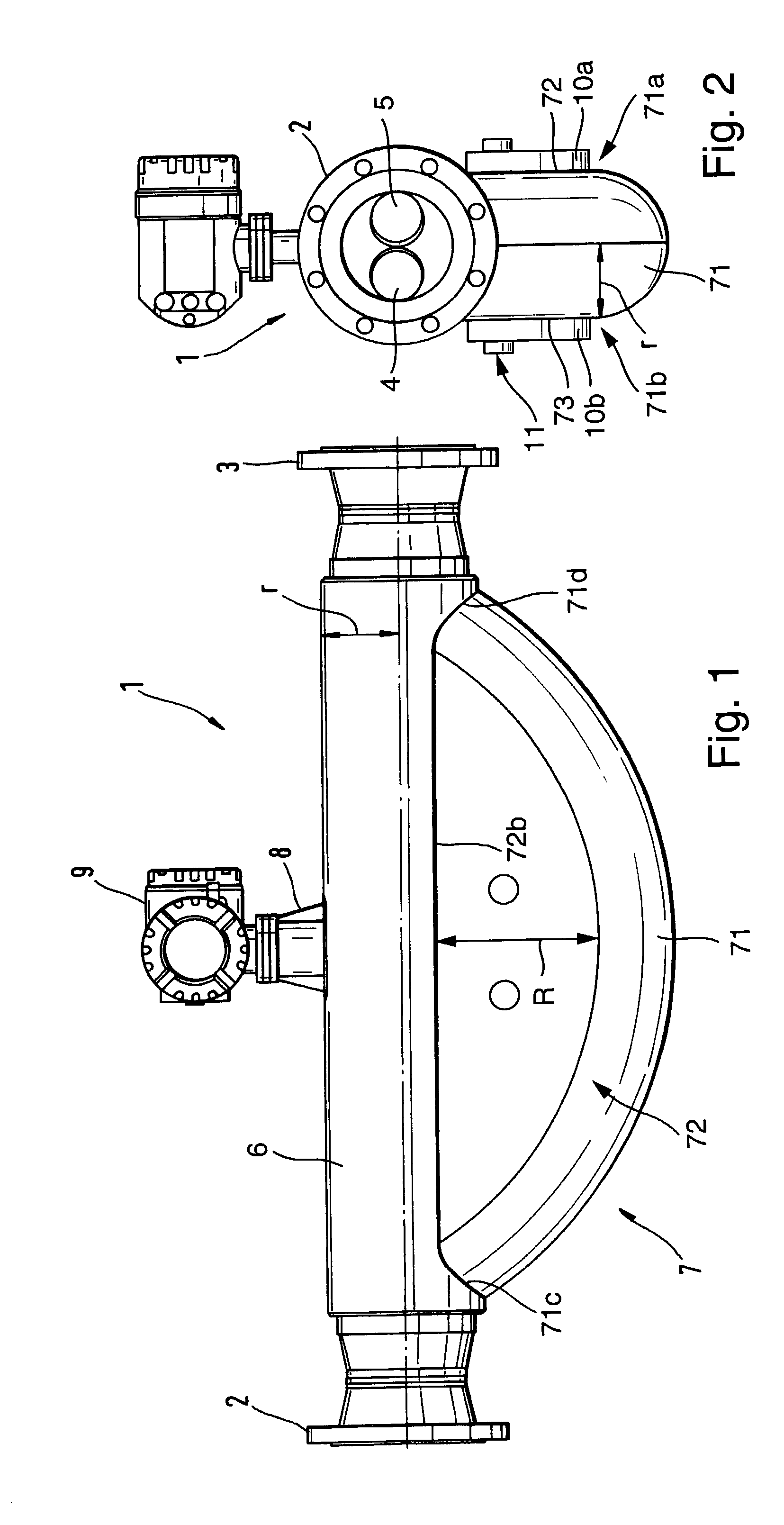
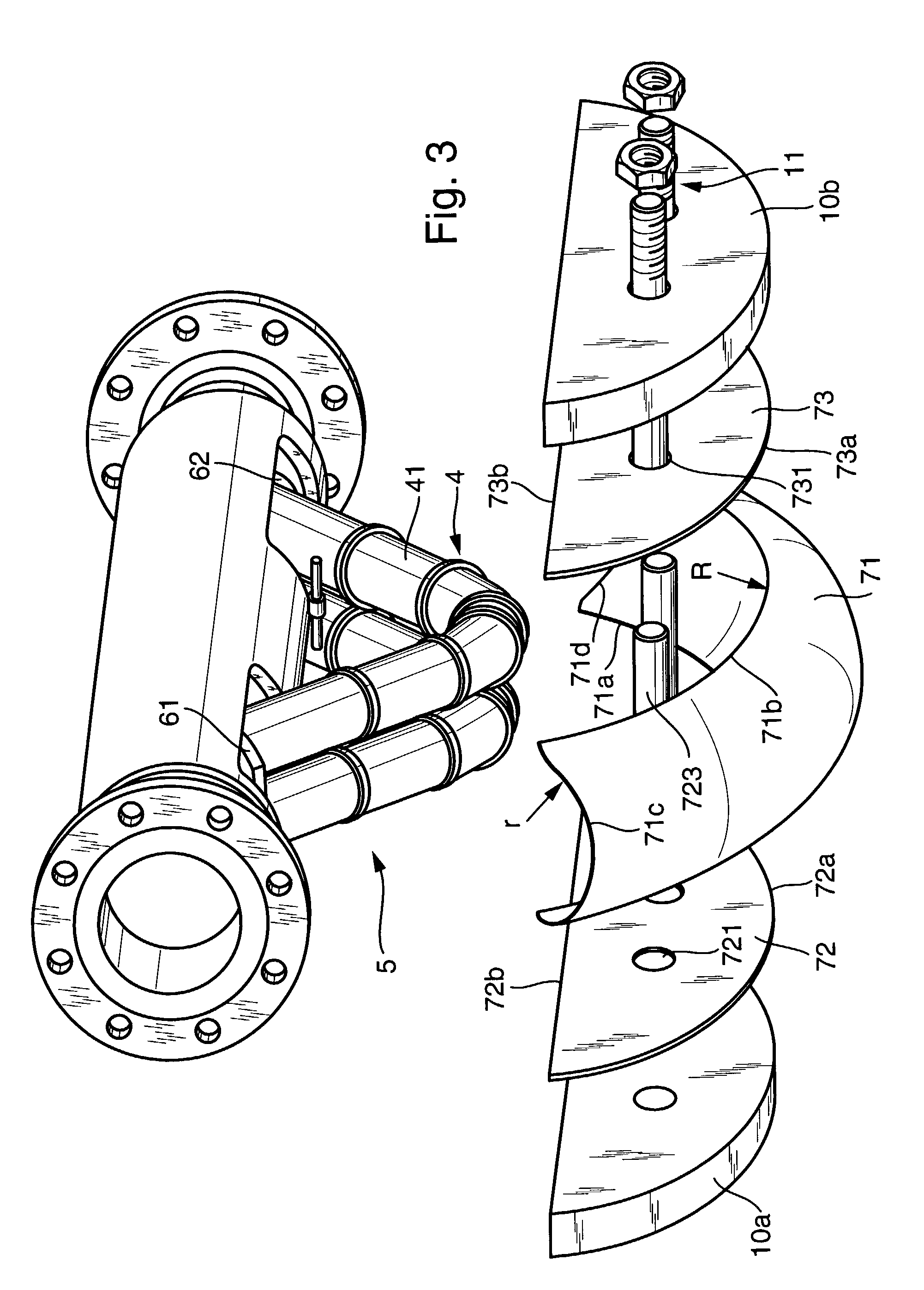
[0040]FIGS. 1 to 4 show, in different representations, a vibratory transducer 1 serving in particular as a Coriolis mass flow, density, and / or viscosity sensor. FIG. 1 is a side view of transducer 1, FIG. 2 is a front view, and FIGS. 3 and 4 are perspective views of transducer 1 from two different angles. In the following, FIGS. 1 to 4 are explained together.

[0041]Transducer 1 is designed to be installed via flanges 2, 3 in a pipe (not shown for clarity) of a given diameter through...


PUM

PropertyMeasurementUnit
thicknessaaaaaaaaaa
radiusaaaaaaaaaa
flexural rigidityaaaaaaaaaa

Abstract

The transducer has a case which is formed by a support frame for supporting a fluid-conducting flow tube and by a case cap for encasing at least one bent segment of the flow tube which vibrates during operation of the transducer. The case cap comprises a channel-shaped first cap segment with a circular-arc-shaped first segment edge of predeterminable radius R and with an essentially identically shaped second segment edge. The first cap segment has a circular-arc-shaped cross section with a radius r less than the radius R of the first segment edge. The case cap further comprises an essentially plane second cap segment, which is connected via a circular-arc-shaped first segment edge with the first segment edge of the first cap segment, and a third cap segment, which is essentially mirror-symmetric with respect to the second cap segment and which is connected via a circular-arc-shaped first segment edge with the second segment edge of the first cap segment. The second and third segments each have a substantially greater flexural rigidity than the first cap segment. The use of the case cap permits the case of the transducer to be made as pressure-resistant as possible at minimum cost.

Description

[0001]This application is based on Provisional Application No. 60 / 315,370, filed Aug. 29, 2001.FIELD OF THE INVENTION[0002]This invention relates to a case cap for a vibratory transducer and to a transducer using such a case cap.BACKGROUND OF THE INVENTION[0003]In process-measurement and automation technology, physical parameters of a fluid flowing in a pipe, such as mass flow rate, density, and / or viscosity, are frequently measured by means of meters which, using a vibratory transducer traversed by the fluid and a measuring and control circuit connected thereto, induce reaction forces in the fluid, such as Coriolis forces corresponding to the mass flow rate and inertial forces corresponding to the density, and derive therefrom a measurement signal representing the respective mass flow rate and / or density of the fluid.[0004]Such mass flowmeters or Coriolis mass flowmeter-densiineters are disclosed, for example, in WO-A 01 / 33174, WO-A 00 / 57141, WO-A 98 / 07009, U.S. Pat. No. 5,796,011,...

Claims


Application Information

Patent Timeline
Patent Type & Authority Patents(United States)
IPC IPC(8): G01F1/84G01F1/76G01F15/14G01N9/00
CPCG01F1/8409G01F1/8477G01F15/14G01N2009/006
Inventor BITTO, ENNIOSCHUTZE, CHRISTIANMOMENTE, OMAR
Owner ENDRESSHAUSER FLOWTECH
Learn More