Fluid measuring device and method

a technology of measuring device and flue, which is applied in the direction of liquid/fluent solid measurement, volume/mass flow by differential pressure, instruments, etc., can solve the problems of measuring flow rate, clogging or bacteria growth, undesirable disturbance of flow, etc., and achieves the effect of preventing damage to the sensing tube and relieving extraneous stresses

Inactive Publication Date: 2005-10-25
THOMAS P KICHER
View PDF22 Cites 53 Cited by
  • Summary
  • Abstract
  • Description
  • Claims
  • Application Information

AI Technical Summary

Benefits of technology

[0008]A pressure transducer and method for measuring pressure of a fluid flow in a tube include use of a sensing tube through which the pressurized flow passes. The sensing tube deforms outward in response to the pressurized flow within. Deformation measuring devices, such as strain gages, measure the outward deformation (axial and / or circumferential strains) and allow computation of the pressure of the flowing fluid. A housing surrounds the sensing tube to relieve extraneous stresses on the sensing tube, to prevent damage to the sensing tube, and to contain any rupture of the sensing tube. The sensing tube and housing may have a round, rectangular, or other shape cross-section. The pressure transducer allows continuous and non-invasive measurement of pressure inside a tube. In addition, a flow restriction such as an orifice may be provided in the sensing tube to enable a flow rate to be determined from the pressure drop across the flow restriction. Further, measuring device for measuring flow rate may utilize a sensing tube that bent (strained) because of forces causes by a change of momentum of flowing fluid due to a direction change of the fluid.

Problems solved by technology

The general problem of measuring flow rates and pressures of flowing fluids and fluid-like substances occurs in a wide variety of circumstances.
Such methods of measuring flow rate may involve undesirable disturbances of the flow and / or possible flow contamination.
In traditional installations, where a pressure probe is offset from the flow, the added volume may entrap the material flowing in the line and present additional problems, such as clogging or bacteria growth.
In a particular exemplary flow measurement problem, that of measuring the pressure of slurries such as liquid concrete flowing in a tube, one method of isolating the slurry flow from the pressure transducer is to inject grease into a fluid line running from the tube to the pressure transducer while the measurement is being made.
However, such a method is not suitable for continuous pressure measurement since grease must be injected before and during measurement.
Such an impurity may be unacceptable, whether the slurry is a flow of concrete, foodstuffs, or some other material.
An example of such a system is shown in U.S. Pat. No. 4,218,926, issued to DeVisser, entitled “Isolating Pressure Sensor.” Such systems have the disadvantages of being complicated and costly, as well as using an elastomeric material such as Buna-N, which may be unsuitable for contact with a corrosive or abrasive fluid or slurry.

Method used


Image

  • Fluid measuring device and method
  • Fluid measuring device and method
  • Fluid measuring device and method

Examples


Embodiment Construction

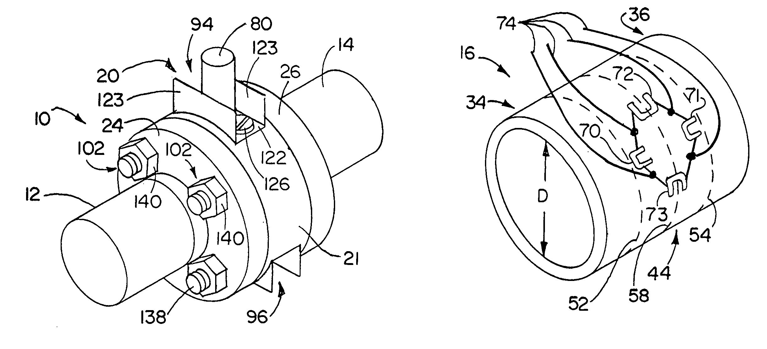
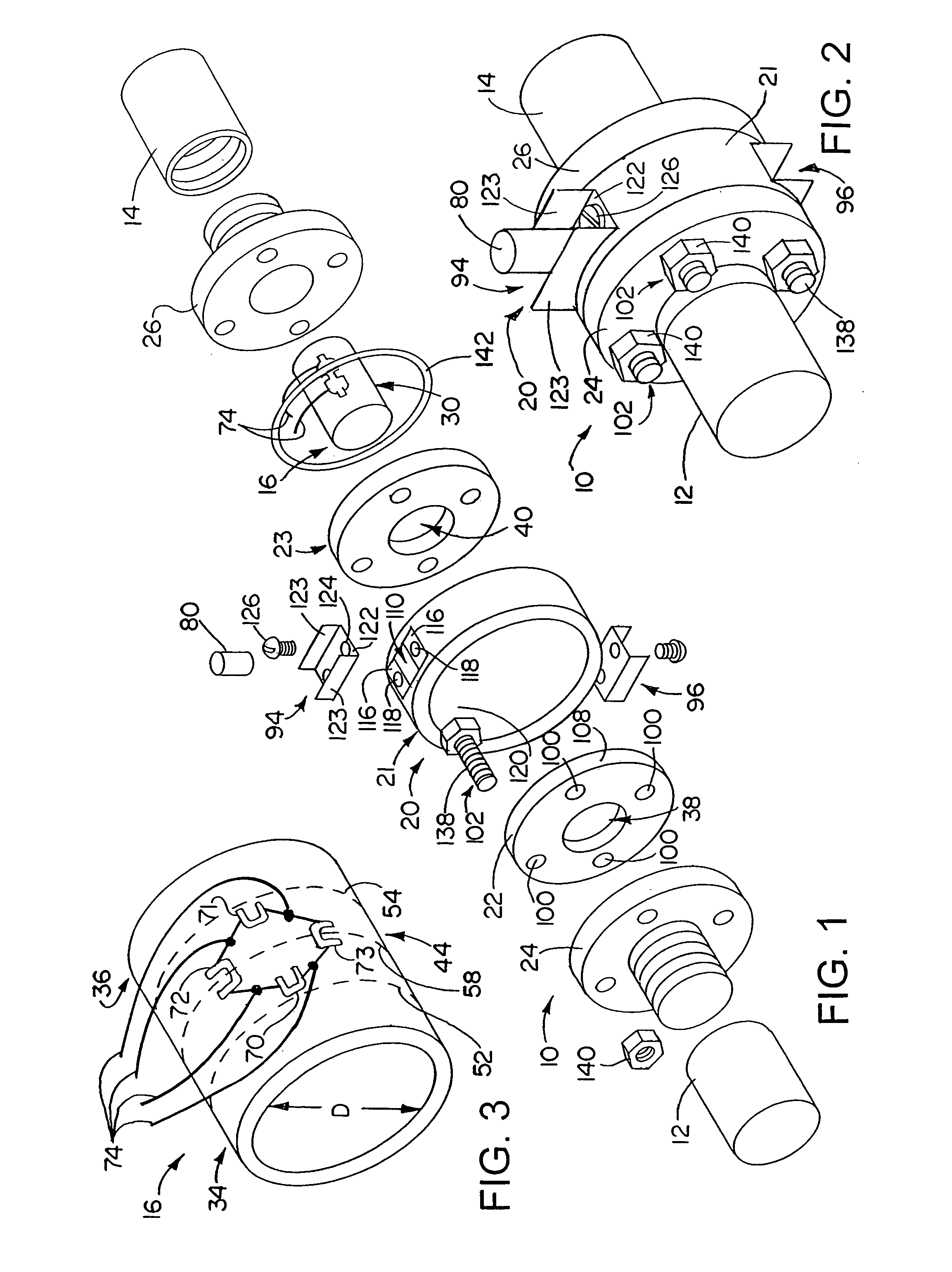
[0044]Referring to FIGS. 1 and 2, a pressure transducer 10 is shown for measuring the pressure of a fluid flow within a pipe, a portion of which is shown generally as pipe segments 12 and 14. The term “fluid,” as used herein, includes liquids, gases, slurries, and multi-phase colloidal and non-colloidal mixtures such as gels, emulsions, fogs, foams, smokes, and gas-liquid, liquid-solid, and gas-solid mixtures, as well as other things that flow. The present invention is particularly useful for measuring pressures of flows of abrasive materials, as well as for measuring pressures in fluid flows were disturbance of the flow is undesirable.

[0045]The pressure transducer 10 includes a sensing tube 16 which is surrounded or encircled by a housing 20. The housing 20 includes a cover 21 which is attached to housing flanges 22 and 23. The sensing tube 16 fits within the housing 20 and is connected to the housing flanges 22 and 23.

[0046]The sensing tube 16 and the housing 20 are coupled to the...


PUM

PropertyMeasurementUnit
tensile strengthaaaaaaaaaa
specific gravityaaaaaaaaaa
pressureaaaaaaaaaa

Abstract

A pressure transducer and method for measuring pressure of a fluid flow in a tube include use of a sensing tube through which the pressurized flow passes. The sensing tube deforms outward in response to the pressurized flow within. Deformation measuring devices, such as strain gages, measure the outward deformation and allow computation of the pressure of the flowing fluid. A housing surrounds the sensing tube to relieve stresses on the sensing tube, to prevent damage to the sensing tube, and to contain any rupture of the sensing tube. The sensing tube may have a round, rectangular, or other shape cross-section. The pressure transducer allows continuous and non-invasive measurement of pressure inside a tube. In addition, a flow restriction such as an orifice may be provided in the sensing tube to enable a flow rate to be determined from the pressure drop across the flow restriction. Further, measuring device for measuring flow rate may utilize a sensing tube that bent (strained) because of forces causes by a change of momentum of flowing fluid due to a direction change of the fluid.

Description

[0001]This application claims the benefit of U.S. Provisional Application No. 60 / 141,506, filed Jun. 28, 1999, which is incorporated herein by reference in its entirety.TECHNICAL FIELD[0002]The present invention relates to pressure and flow rate transducers and methods for measuring pressure and flow rate. More particularly, the present invention relates to transducers and methods for measuring pressure of fluid flowing in a tube.BACKGROUND OF THE INVENTION[0003]The general problem of measuring flow rates and pressures of flowing fluids and fluid-like substances occurs in a wide variety of circumstances. Methods of measuring flow rates in a pipe often involve insertion of a probe or diversion of a portion of the flowing fluid. Such methods of measuring flow rate may involve undesirable disturbances of the flow and / or possible flow contamination. In traditional installations, where a pressure probe is offset from the flow, the added volume may entrap the material flowing in the line ...

Claims


Application Information

Patent Timeline
Patent Type & Authority Patents(United States)
IPC IPC(8): G01L9/00
CPCG01L9/0027
Inventor KICHER, THOMAS P.KICHER, PAUL T.
Owner THOMAS P KICHER
Why Eureka
Try Eureka