Apparatus and method for braking ergonomic support actuator

a technology of ergonomic support and actuator, which is applied in the direction of cycle brakes, mechanical control devices, process and machine control, etc., can solve the problems of increasing the cost of the actuator both in terms of the number of parts required and their assembly, and devices that do not wear well, etc., to achieve the effect of quick response to the pressure on the pin

Inactive Publication Date: 2005-10-25
L & P PROPERTY MANAGEMENT CO
View PDF59 Cites 18 Cited by
  • Summary
  • Abstract
  • Description
  • Claims
  • Application Information

AI Technical Summary

Benefits of technology

[0014]The housing and disk have complementary friction surfaces. The Bowden cable wire is mounted on the disk so that rotation of the disk in a first direction exerts tractive force on the wire and rotation of disk in the opposite direction releases tension on the wire. This force is imparted to the disk by the user turning the lever, causing the pins to push the disk. The engagement of the friction surfaces on the disk with the friction surfaces on the housing are sufficient to brake the rotation of the disk against the return pressure on the wire exerted by the pressure of the seat occupant on the ergonomic support surface. The braking friction surfaces are given mechanical advantage over the force on the Bowden cable wire by being placed at a greater radial distance from the axis of the disk than the seat of the Bowden cable wire.
[0016]The lever has pins fixedly attached to it. These pins are parallel to the axis of the disk and extend through slots in the housing. Inside the housing, the pins engage holes in the disk. The edges of these holes comprise loading surfaces against which the pins push to first release the brake and secondly move the disk in one rotational direction or the other. In one preferred embodiment, there are two pins, two pin slots in the housing and two loading surface holes to receive the pins in the disk. In one preferred embodiment, the loading surface holes are oblong and nonparallel, in order that the disk may quickly respond to pressure on the pins.
[0017]The disk has an axle which is mounted in an axle housing seat. In order to allow the slight but necessary upwards movement of the disk out of engagement with the frictional surfaces of the housing, thereby releasing the brake, the axial housing mount for the disk axle is oval shaped. This shape gives the disk axle room to move upwards, and thereby to move the disk up and out of braking engagement with the housing.

Problems solved by technology

Prior art actuators achieve these design goals through mechanisms that were complex, and therefore expensive, See, for example, U.S. Pat. No. 5,794,479, U.S. Pat. No. 6,178,838, U.S. Pat. No. 6,230,867 B1.
The use of such overrunning clutches, ratchets, bearings, and eccentric rings involve a large number of parts, increasing the expense of the actuator both in terms of the number of parts required and their assembly.
Moreover, such devices do not wear well and tend to break or slip after a number of use cycles shorter than the predicted lifetime of the seat in which they are installed.

Method used


Image

  • Apparatus and method for braking ergonomic support actuator
  • Apparatus and method for braking ergonomic support actuator
  • Apparatus and method for braking ergonomic support actuator

Examples


Embodiment Construction

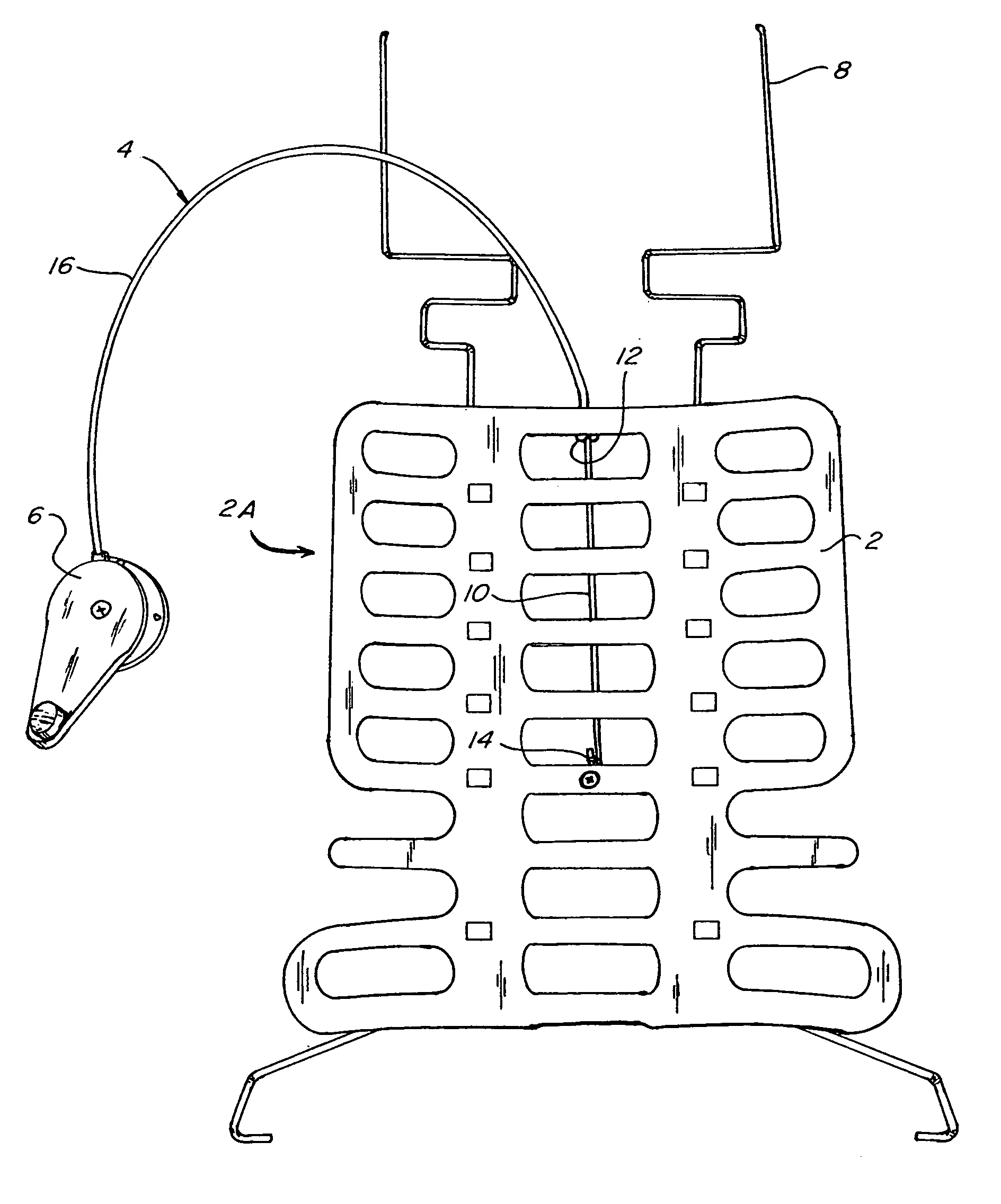
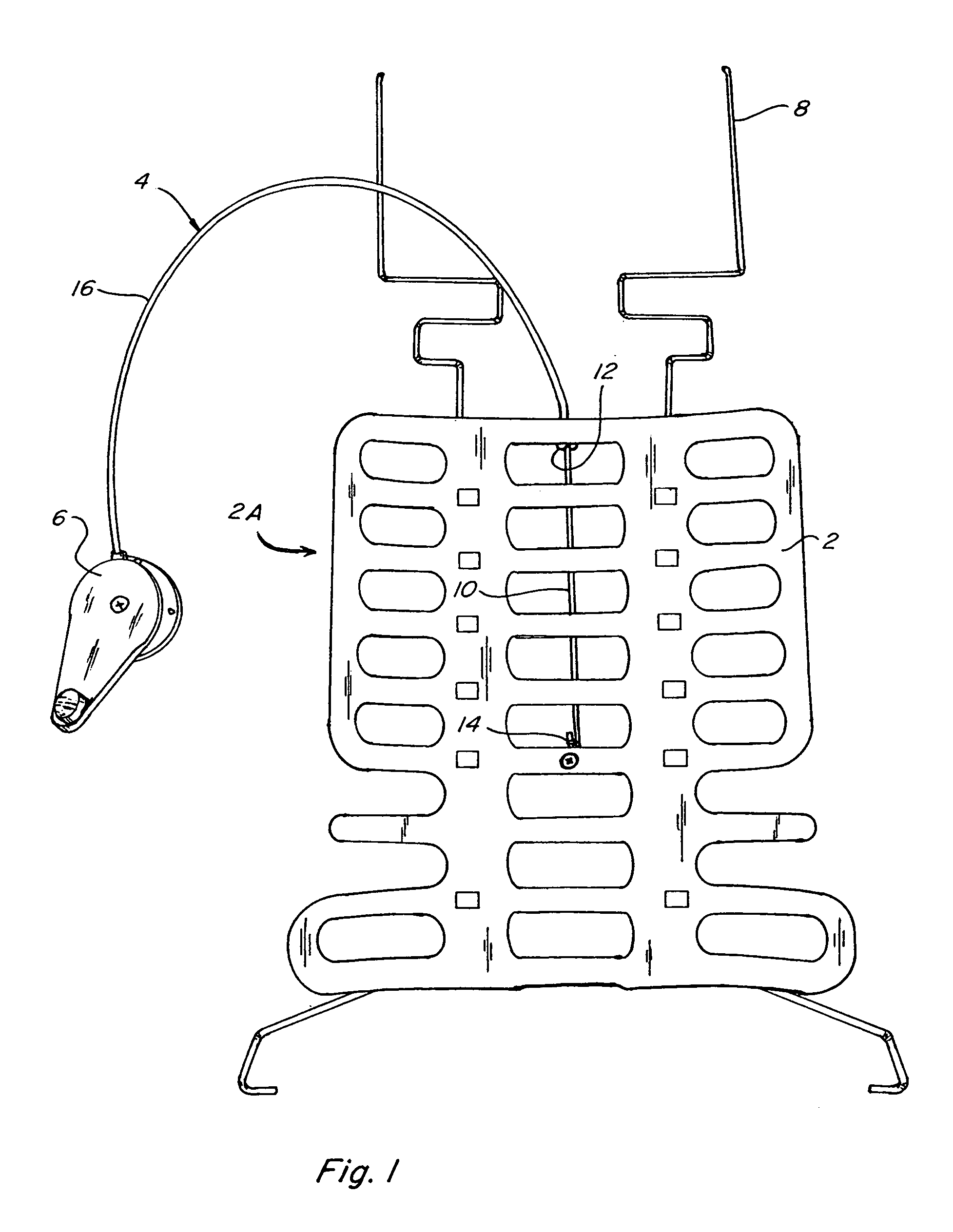
[0029]Referring to the accompanying drawings in which like reference numbers indicate like elements, FIG. 1 illustrates a continuously positionable lumbar support and its relationship to a Bowden cable 4 and actuator 6. The pressure surface 2 is mounted to guide rails 8 and at least one portion of the arching pressure surface 2 slides up and down along guide rails 8. Bowden cable 4 includes a Bowden cable wire 10. A Bowden cable sleeve 16 is mounted to one end of the arching pressure surface 2 at a sleeve mount 12. The Bowden cable wire 10, which slides axially through the Bowden cable sleeve 16, is mounted to another portion of the arching pressure surface 2, at Bowden cable wire mount 14. When actuator 6 is engaged, it puts traction on the Bowden cable wire 10 drawing it axially into Bowden cable sleeve 16. This is turn puts tractive force on the arching pressure surface 2 at the Bowden cable wire mount 14 drawing it and the Bowden cable sleeve mount 12 closer together. This cause...


PUM


Abstract

A braking actuator for an ergonomic support is connected thereto by a Bowden cable. The actuator has a housing with pin slots, friction surfaces and a mount for a disk axle. A disk has frictional surfaces, holes with pin load edges, a Bowden cable wire seat that holds the Bowden cable end and an axle that is supported by the mount in the housing. The friction surfaces of the disk and housing engage each other to brake the actuator and the ergonomic support. A lever having pins is disposed on the housing such that the pins extend through the pin slots to engage the holes in the disk. Turning the lever disengages the friction surfaces and rotates the disk, thereby moving the ergonomic support. Releasing the lever engages the frictional surfaces such that movement of the ergonomic support is braked at a selected position.

Description

STATEMENT REGARDING FEDERALLY SPONSORED RESEARCH OR DEVELOPMENT[0001]Not Applicable.CROSS-REFERENCE TO RELATED APPLICATIONS[0002]None.APPENDIX[0003]Not Applicable.BACKGROUND OF THE INVENTION[0004]1. Field of the Invention[0005]The invention is an actuator used to move and hold ergonomic supports for seats and chairs.[0006]2. Related Art[0007]Automobile and furniture seats frequently include ergonomic supports, such as lumbar supports. There are several types of lumbar supports, including arching pressure surfaces, See, e.g. U.S. Pat. No. 5,397,164, push paddle type lumbar supports, See, e.g. U.S. Pat. No. 4,295,681, and strap type supports, See, e.g. U.S. patent application Ser. No. 09 / 485,738. The common features shared by all these varieties of ergonomic support include being continuously positionable and being operated by an actuator installed on an exterior surface of the seat so that it can be controlled by person sitting in the seat. Many of these actuators are manual, mechani...

Claims


Application Information

Patent Timeline
Patent Type & Authority Patents(United States)
IPC IPC(8): B60N2/66B60N2/64
CPCB60N2/66Y10T74/20438Y10T74/20408Y10T74/20486Y10T74/2042Y10T74/2048B60N2/6671
Inventor KOPETZKY, ROBERTFRANK, RICHARD
Owner L & P PROPERTY MANAGEMENT CO
Why Eureka
Try Eureka