Cleaning attachment for fluid dispenser nozzles and fluid dispensers using same

a technology of fluid dispenser nozzle and cleaning attachment, which is applied in the direction of liquid handling, lighting and heating apparatus, combustion types, etc., can solve the problems of inability to achieve positive flow cutoff in the filling apparatus using conventional sanitary filling valves, inability to achieve positive flow cutoff in the filling apparatus, and inability to control the weight of packaged cheese. to achieve the effect of easy disassembly and assembly

Inactive Publication Date: 2005-10-25
INTERCONTINENTAL GREAT BRANDS LLC
View PDF13 Cites 17 Cited by
  • Summary
  • Abstract
  • Description
  • Claims
  • Application Information

AI Technical Summary

Benefits of technology

[0006]This invention provides an improved nozzle attachment for removing residual material from the discharge ends of dispenser nozzles used for dispensing flowable materials. The invention also provides a dispenser incorporating the improved nozzle attachment and methods of their use in filling procedures. According to an embodiment, the nozzle attachment of this invention is an assembly of a relatively small number of discrete parts that can be readily assembled into a unified component for installation on a nozzle, and which also can be easily dismantled into its individual parts for inspection and cleaning-out-of-place or manual cleaning. Therefore, in one aspect, the nozzle attachment is conveniently used for sanitary dispensing applications, although not limited thereto. In one aspect, no tools are required to couple the nozzle attachment to a nozzle nor are they needed to dismantle it for inspection and cleaning, as the device can be assembled and disassembled completely by hand.
[0011]This nesting configuration of the two components also defines a lower gas passageway having a gas discharge opening that is defined between the outward-facing beveled surface of the inner nozzle attachment component and the inward-facing beveled surface of the outer nozzle attachment component. The lower gas passageway is in fluid communication with the upper gas passageway. The lower gas passageway is adapted by its configuration to direct pressurized gas at an inward and downward angle at the discharge end of the nozzle. The gas emitted by the nozzle attachment at the discharge opening creates a shearing force at the discharge end of the nozzle that will dislodge and remove any residual material clinging to the discharge end after the most recent dispensing operation. This ensures all product dispensed per dispensing cycle gets packaged in that cycle, and that uniform amounts of food are dispensed in each dispensing cycle. Herein, the nested components are easily assembled or disassembled by moving the nested inner component axially relative to the outer component. This allows quick separation for cleaning and re-assembly after cleaning.
[0012]In another embodiment, there is a fluid dispenser for use in intermittent dispensing operations that incorporates the nozzle attachment described herein. The dispenser includes a dispenser body having a fluid inlet communicating with a fluid passageway, and the discharge nozzle having the discharge end from which fluid is dispensed. There is a valve stem positioned within the fluid passageway adapted to be controllably moved vertically up and down within the fluid passageway by an actuator. A valve head is located in the discharge end of the discharge nozzle. The nozzle attachment is used after each dispensing cycle to eliminate residue clinging from the discharge end of the nozzle.

Problems solved by technology

Positive flow cut off of a filling apparatus is difficult to achieve in sanitary valves, especially when viscous fluids are being dispensed which have a tendency to leave tailings that cling to the dispenser nozzle after a dispensing cycle.
For example, when running hot process cheese at 160 to 180 degrees Fahrenheit, it is difficult to achieve positive flow cutoff in a filling apparatus using conventional sanitary filling valves.
This retention can lead to unacceptable variability in weight control for the packaged cheese.
In addition, the residue can become dislodged at a later time, and possibly drip or otherwise drop onto an underlying conveyor belt or other surfaces.
Removal of the drip or tailing residues from the nozzle by mechanical or manual means is generally difficult or overly burdensome in practice.
However, these approaches require fundamental design changes in the dispenser head or filling valve construction.

Method used


Image

  • Cleaning attachment for fluid dispenser nozzles and fluid dispensers using same
  • Cleaning attachment for fluid dispenser nozzles and fluid dispensers using same
  • Cleaning attachment for fluid dispenser nozzles and fluid dispensers using same

Examples


Embodiment Construction

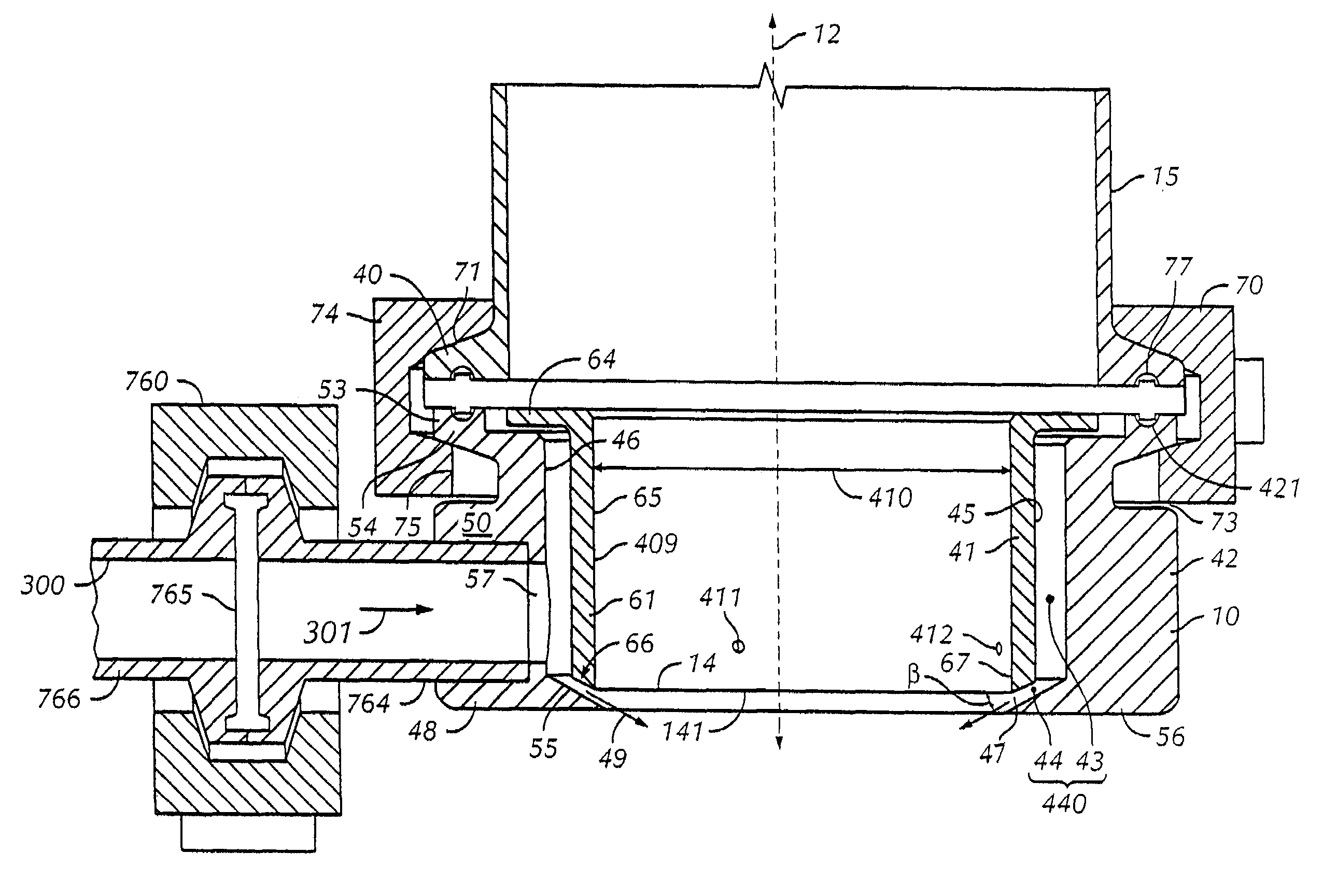
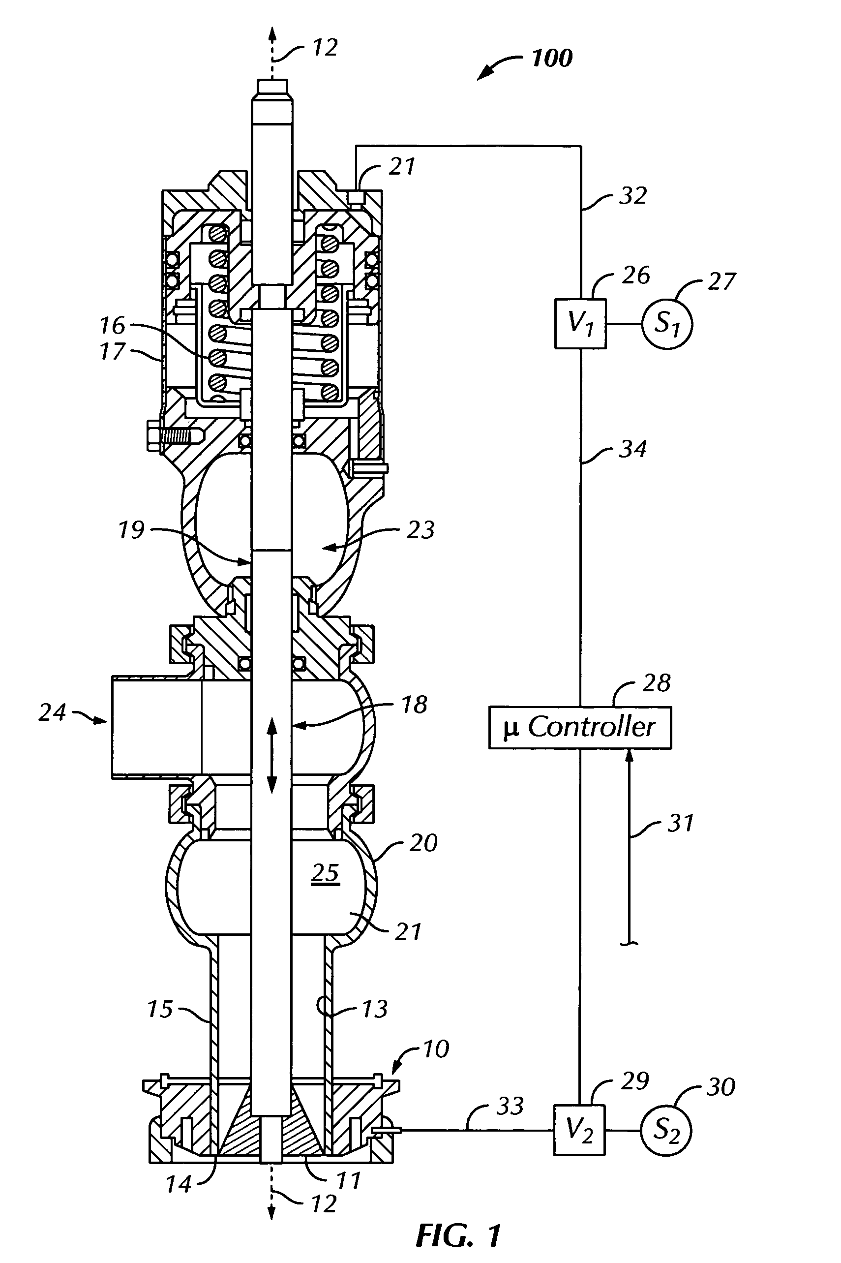
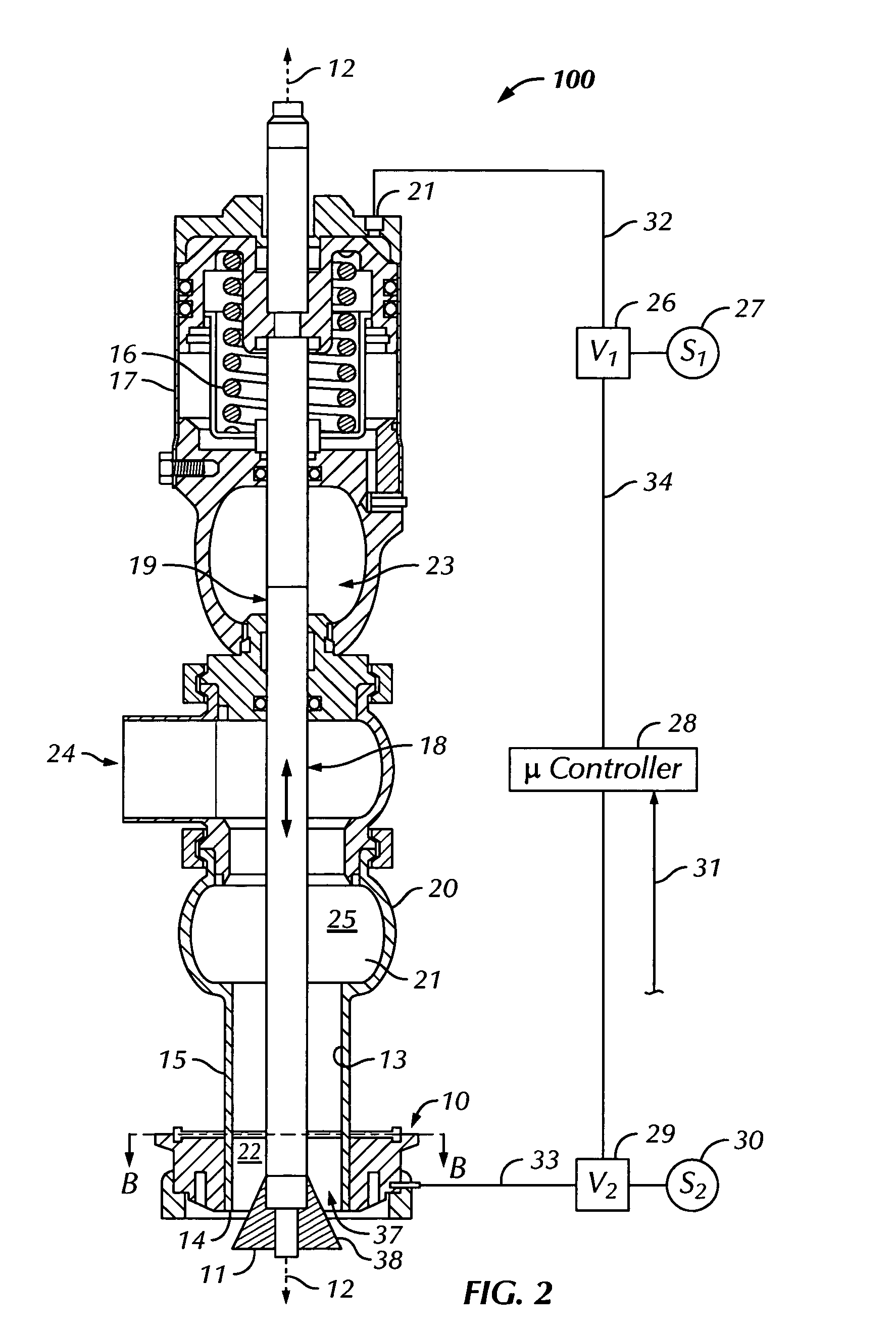
[0025]Referring to FIG. 1, a fluid dispenser 100 having a nozzle attachment 10 according to an embodiment of the invention is illustrated. A general overview of the manner in which the dispenser 100 functions is provided as follows. Axial movement of the valve head 11 up or down in the vertical direction to operate the dispenser 100 occurs in the following manner. For purposes of the descriptions herein, references to an axial direction means parallel to the direction of the centerline 12 of the dispenser 100, while a radial direction will be perpendicular thereto.

[0026]The valve head 11 is normally maintained in a closed position in which it is seated against the inner walls 13 of the discharge end 14 of the nozzle 15 in a sealing relationship. The dimensions of the valve head 11 and inner walls 13 at the discharge end 14 of the nozzle 15 are machined to have very close tolerances so that an essentially gap-free seal is made between the valve head 11 and the inner walls 13 of the v...


PUM


Abstract

A nozzle attachment for removing residual material retained on the dispensing nozzle of a fluid dispenser, having a retainer adapted to releasably attach the nozzle attachment to a dispensing nozzle, and a pair of hollow-bodied nozzle attachment components that define, when nested together, an intervening space useful as a gas passageway for pressurized gaseous fluid introduced and directed to a discharge opening at a lower axial end of the nested nozzle attachment components. The gas passageway is adapted to emit gas introduced into the gas passageway as a gas stream in a manner effective to remove residual material clinging to the nozzle. Dispensers using the nozzle attachment are presented, including one using a truncated valve head.

Description

FIELD OF THE INVENTION[0001]The present invention generally relates to a nozzle attachment for removing residual material retained on the dispensing nozzle of a fluid dispenser by a gas flow at a discharge nozzle during intermittent fluid dispensing operations involving opening and shutting off of a fluid dispenser. The gas flow creates a shearing force at the discharge end of the nozzle that dislodges and blows off any residual material clinging to the discharge end after a prior dispensing operation or cycle.BACKGROUND OF THE INVENTION[0002]Positive flow cut off of a filling apparatus is difficult to achieve in sanitary valves, especially when viscous fluids are being dispensed which have a tendency to leave tailings that cling to the dispenser nozzle after a dispensing cycle. For example, when running hot process cheese at 160 to 180 degrees Fahrenheit, it is difficult to achieve positive flow cutoff in a filling apparatus using conventional sanitary filling valves. Upon full clo...

Claims


Application Information

Patent Timeline
Patent Type & Authority Patents(United States)
IPC IPC(8): B05B15/02B67C3/00F23G5/44F23D11/38F23D11/36B65B39/00
CPCB05B15/025B67C3/001F23D11/386F23G5/446B65B2210/08B05B15/55
Inventor GOWENS, PATRICK A.AAFEDT, RYAN
Owner INTERCONTINENTAL GREAT BRANDS LLC
Why Eureka
Try Eureka