Magnet mounting structure

a technology for mounting structures and magnets, applied in the direction of linear/angular speed measurement, speed/acceleration/shock instrument details, building scaffolds, etc., can solve the problem that thin and flat magnets cannot generate a magnetic flux of a sufficiently high density in the direction perpendicular to their, and achieve the effect of lessening the risk of magnet being partially chipped, reducing the axial magnetic flux, and easy chipping

Inactive Publication Date: 2005-10-25
CATEYE
View PDF13 Cites 27 Cited by
  • Summary
  • Abstract
  • Description
  • Claims
  • Application Information

AI Technical Summary

Benefits of technology

[0014]The magnetic material is brittle and thus easily chipped off at its corners. Then, the corners of the magnet are cut off and the side thereof is covered in order to avoid the corners from being exposed and thus lessen the risk that the magnet is partially chipped off. If any material with a high magnetic permeability is used to cover the side, the axial magnetic flux passes through the high-permeability material on the side and thus the axial magnetic flux decreases. Therefore, a nonmagnetic material is used to cover the side. Alternatively, the magnet may entirely be covered with a high tough material so that the top surface of the magnet is covered and no surface thereof is exposed. The material covering the top surface of the magnet may be either of a nonmagnetic material and a high-permeability material. When

Problems solved by technology

For example, a thin and flat magnet cannot generate a magnetic flux of a s

Method used


Image

  • Magnet mounting structure
  • Magnet mounting structure
  • Magnet mounting structure

Examples


Embodiment Construction

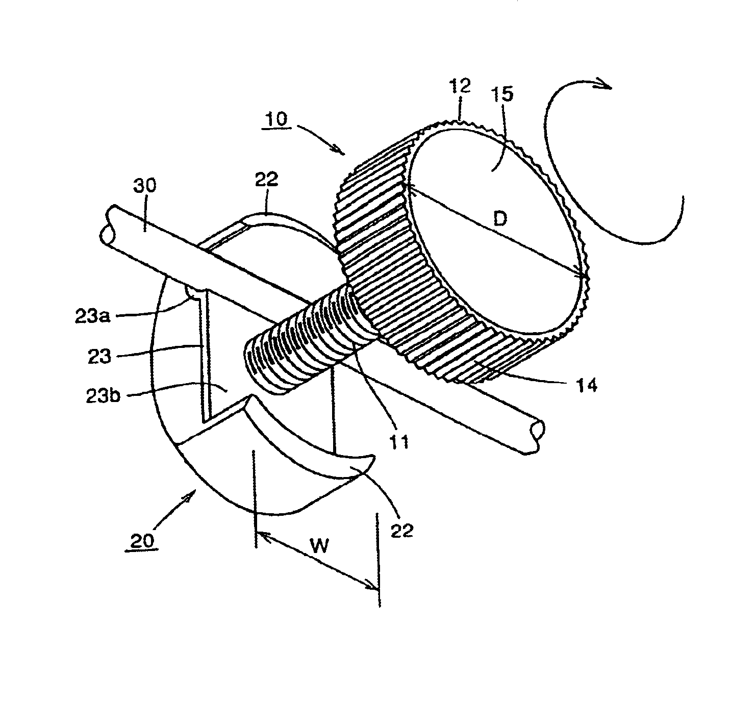
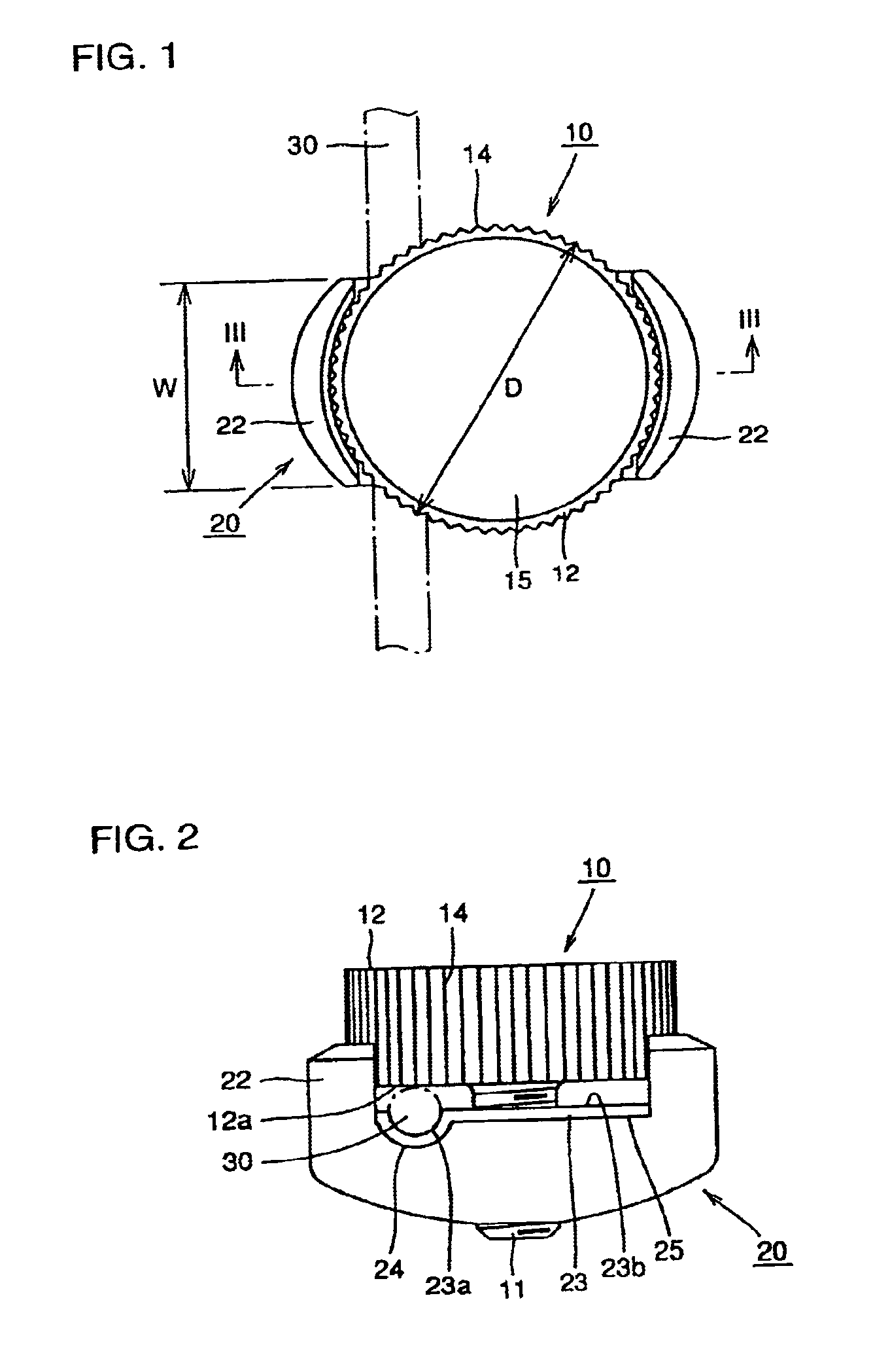
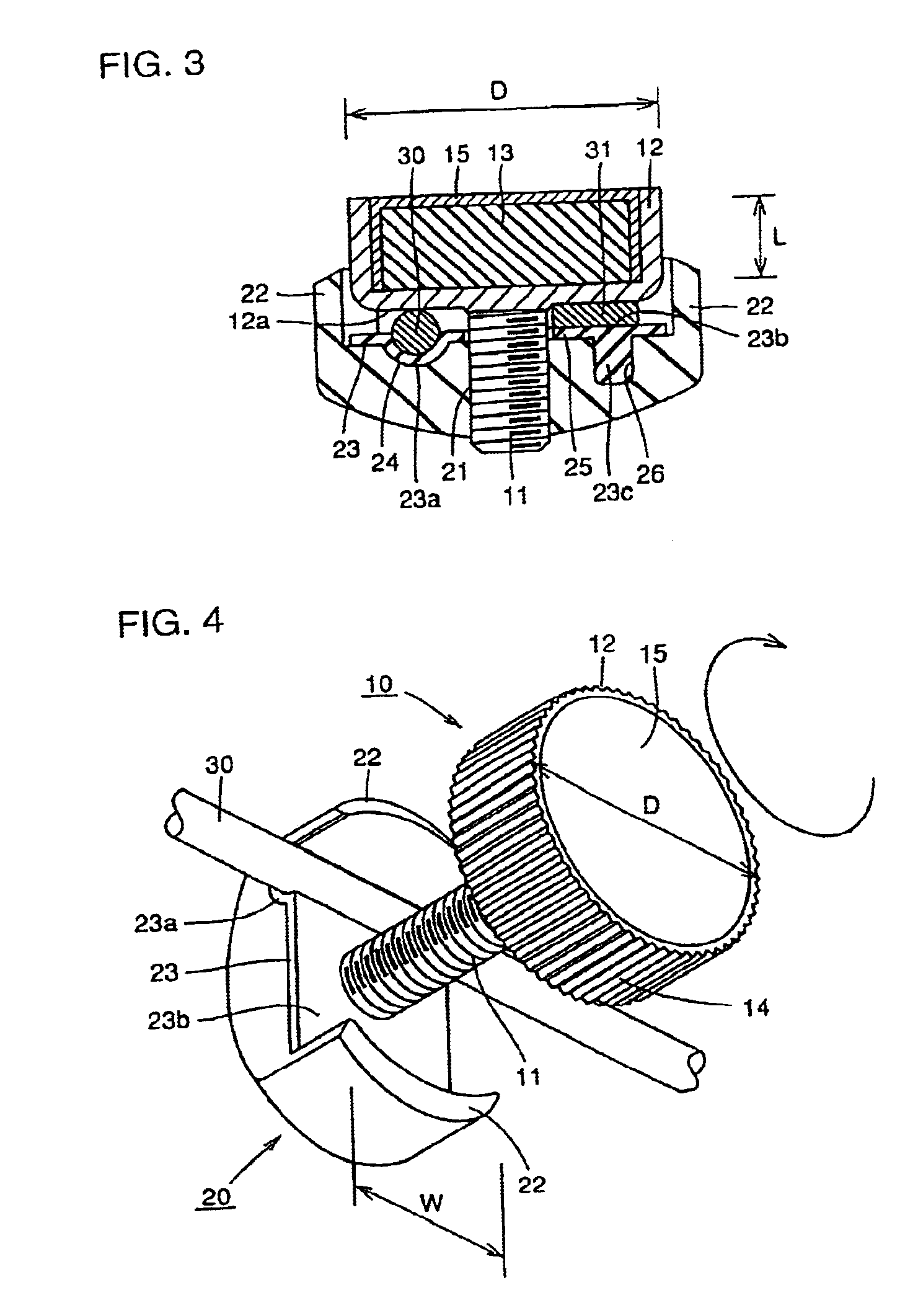
[0040]An embodiment of the present invention is now described in conjunction with the drawings. FIG. 1 is a plan view of a magnet mounting structure according to the embodiment of the invention. Grooves 14 are cut on the lateral periphery of a head portion 12 of a knob member 10 in order to facilitate screwing of knob member 10 by fingers. An internal thread member 20 has two projections 22 so that knob member 10 is sandwiched therebetween in order to prevent internal thread members 20 from departing from a spoke 30. The longitudinal direction of internal thread member 20 is along the direction connecting two projections 22. The width of internal thread member 20 is in the direction perpendicular to this longitudinal direction. The width W is a smaller than the diameter D of head portion 12 of knob member 10. The periphery of head portion 12 of knob member 10 is thus locate outside internal thread member 20 so that knob member 10 can easily be turned by finger surfaces.

[0041]FIG. 2 ...


PUM


Abstract

A magnet mounting structure for fastening a magnet to a spoke of a two-wheeled vehicle even without tool includes a knob member having a screw and the magnet and an internal thread member in which the screw is screwed. The spoke is held between the knob member and the internal thread member to allow the magnet to be fastened to the spoke.

Description

RELATED APPLICATION[0001]This application is a continuation of patent application Ser. No. 09 / 922,561 filed Aug. 3, 2001, now abandoned which claimed priority of Japanese application Ser. No. 2000-252518(P) filed Aug. 23, 2000.BACKGROUND OF THE INVENTION[0002]1. Field of the Invention[0003]The present invention relates to a structure for mounting a magnet. Specifically, the invention relates to a magnet mounting structure for attaching a magnet which renders a signal to a sensor to detect the running speed of a two-wheeled vehicle.[0004]2. Description of the Background Art[0005]An increasing number of bicycles employ a speedometer mounted thereto for facilitating ascertainment of the travelling speed, travelling distance and the like of the bicycles. FIG. 5 is an external view of a bicycle incorporating a speedometer therein and FIG. 6 is an enlarged view of the portion indicated by X in FIG. 5. A signal generator / transmitter portion is constituted of a transmitter unit 128 detachab...

Claims


Application Information

Patent Timeline
IPC IPC(8): B62J11/00G01P3/42G01P1/02G01P3/487G01P1/00F16B2/02F16B2/06B62J99/00
CPCB62J11/00G01P1/026G01P3/487F16B2/065Y10T403/71Y10S403/01Y10T403/7067Y10T24/3958B62J45/412B62J45/423
Inventor OKUDA, YOJI
Owner CATEYE
Why Eureka
Try Eureka