Low power parking brake force adjustment apparatus and method for electrically actuated brake systems

a technology of brake force adjustment and parking brake, which is applied in the direction of braking systems, braking components, transportation and packaging, etc., can solve the problems of limited power availability and difficulty in providing compensation for brake force variations, and achieve the effect of reducing power consumption

Inactive Publication Date: 2005-11-01
THE BF GOODRICH CO
View PDF22 Cites 35 Cited by
  • Summary
  • Abstract
  • Description
  • Claims
  • Application Information

AI Technical Summary

Benefits of technology

[0005]The present invention provides for low power parking force adjustment by means of brake force monitoring and actuator control that minimizes power consumption from the vehicle power source such as a battery. The system uses a lower power circuit to monitor the force applied to the brake stack, control the primary power to the power brake actuation system and command the brake actuation system to adjust the force whenever the parking brake force exceeds a preset limit.
[0007]Accordingly, the present invention offers the advantages of being more accurate and consistent in maintaining parking brake forces under all environmental conditions, and minimizing power consumption by limiting power to the actuation system.

Problems solved by technology

One problem in such known systems resides in the difficulty in providing compensation for brake force variations due to external factors such as temperature.
Another problem relates to there oftentimes being limited power availability when the vehicle is in a parking brake condition (e.g., the vehicle has been parked and shut down).

Method used


Image

  • Low power parking brake force adjustment apparatus and method for electrically actuated brake systems
  • Low power parking brake force adjustment apparatus and method for electrically actuated brake systems
  • Low power parking brake force adjustment apparatus and method for electrically actuated brake systems

Examples


Embodiment Construction

[0019]The present invention will now be described with reference to the drawings, wherein like reference labels are used to refer to like elements throughout.

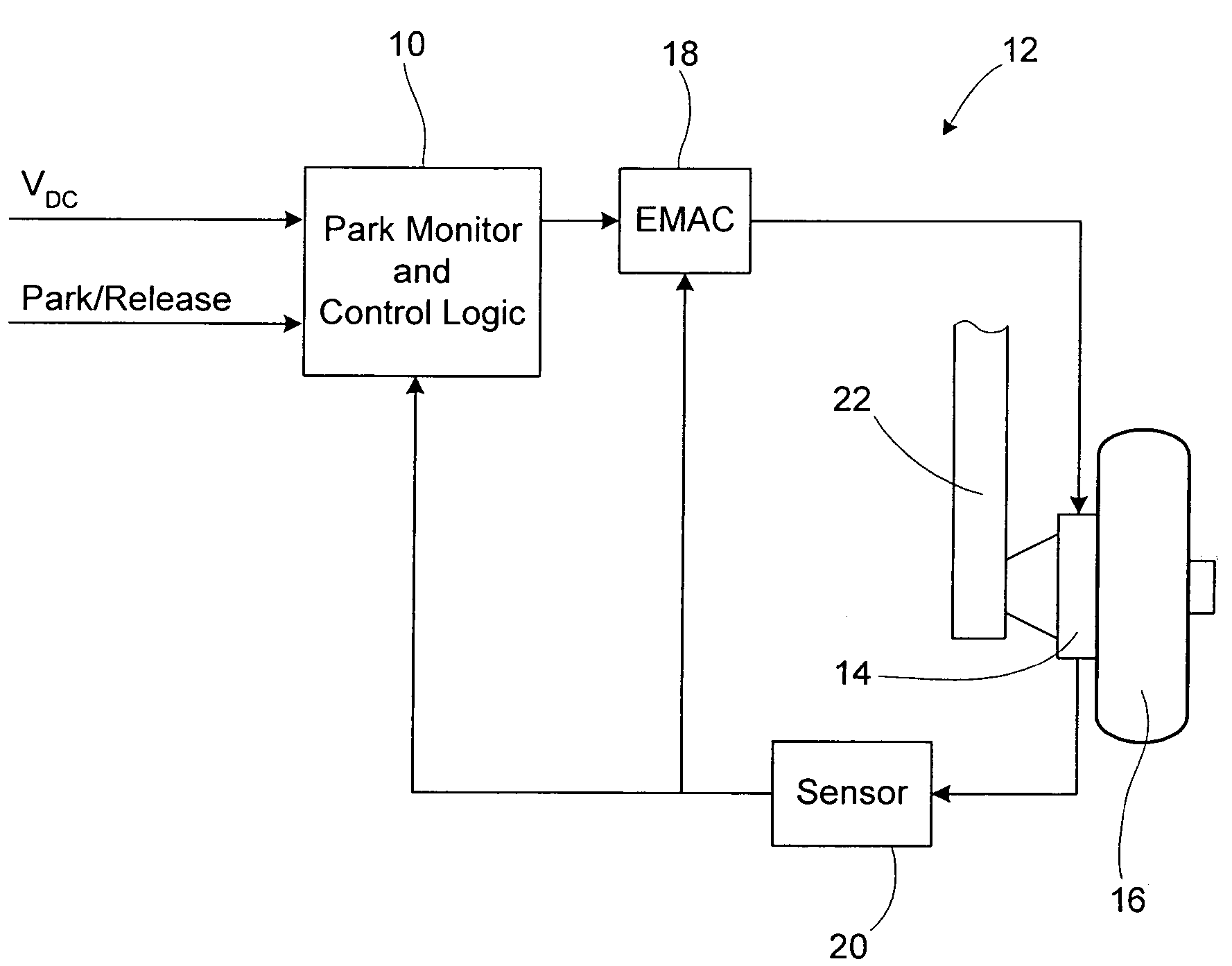
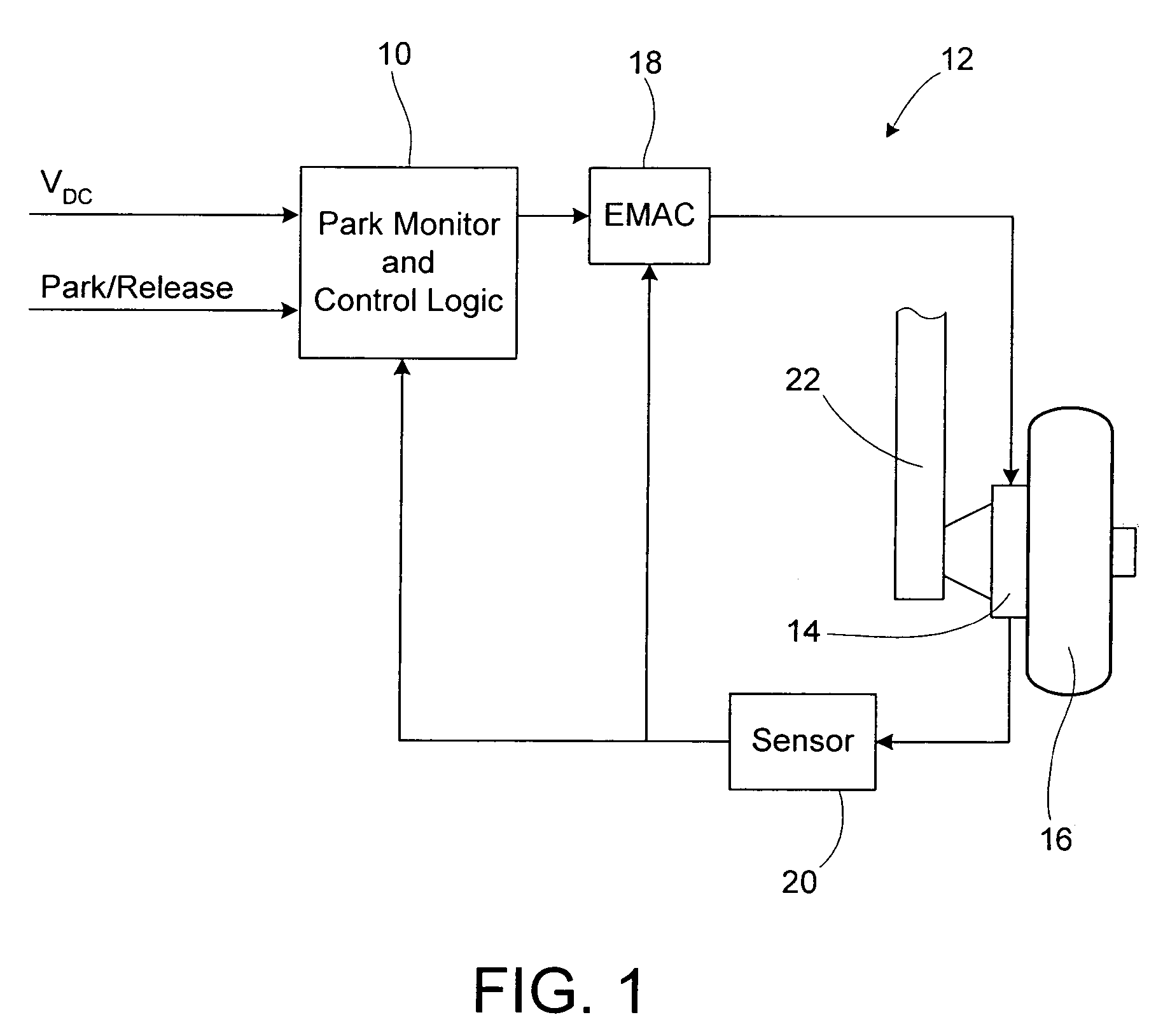
[0020]Referring initially to FIG. 1, a parking brake monitor and adjustment control system for controlling parking brake operation of an electromechanically actuated brake system is shown. The parking brake monitor and adjustment control system, generally designated 10, monitors and controls a brake system 12. In the exemplary embodiment, the brake system 12 includes one or more electromechanical actuators 14 for applying a parking brake force to one or more wheels 16 of a vehicle.

[0021]The brake system 12 further includes an electromechanical actuator controller (EMAC) 18 configured to provide appropriate driving signals to the actuator(s) 14 in response to park and release command signals. In addition, the brake system 12 includes one or more sensors 20 for providing a feedback signal to the control system 10 and / or EMAC 18. ...


PUM


Abstract

A parking brake monitor and adjustment control system controls parking brake operation of an electromechanically actuated brake system which applies a parking brake force to a wheel. The system includes a monitor circuit for producing an output signal which intermittently causes the brake system to readjust the parking brake force applied to the wheel.

Description

TECHNICAL FIELD[0001]The present invention relates generally to electromechanical braking systems. More particularly, the present invention relates to an apparatus and method for providing controlled parking brake operation in an electromechanically actuated brake.BACKGROUND OF THE INVENTION[0002]Electromechanical brake systems are known in the prior art. In such systems, electric motor-driven actuators are used in connection with the operation of the parking brake of a vehicle. Examples of such known systems are presented by the patents to Masayoshi Matsuo et al. U.S. Pat. No. 4,629,043, and Taber et al. U.S. Pat. No. 3,539,038. Furthermore, the use of a solenoid to release the pawl of a parking brake system is disclosed in the prior patent to Fasano U.S. Pat. No. 4,265,345.[0003]One problem in such known systems resides in the difficulty in providing compensation for brake force variations due to external factors such as temperature. Another problem relates to there oftentimes bei...

Claims


Application Information

Patent Timeline
Patent Type & Authority Patents(United States)
IPC IPC(8): B60T7/02B60T7/10B60T17/22B60T13/74B60T13/00B60T17/18
CPCB60T7/085B60T7/107B60T8/1703B60T13/741B60T17/221
Inventor RALEA, MIHAICAHILL, ERIC DANIEL
Owner THE BF GOODRICH CO
Why Eureka
Try Eureka