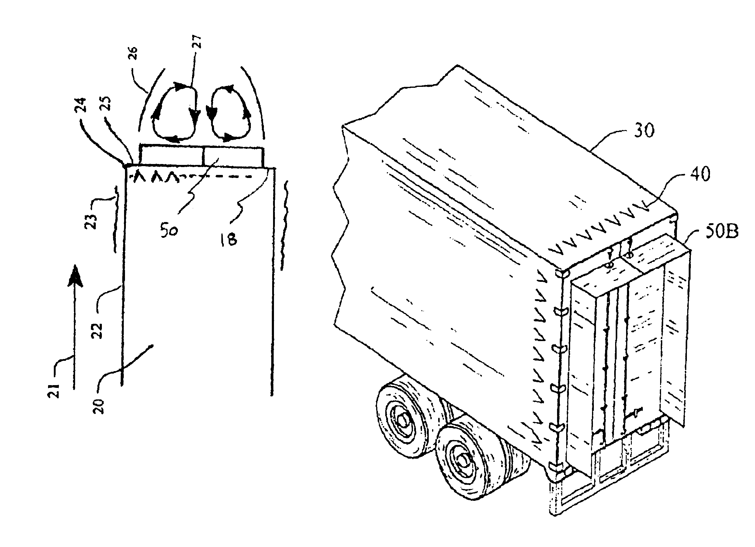
The static pressure on the base surface is reduced as a consequence, thus causing base drag.
But the reverse is not true.
Flow conditions at the forebody, and along the side surfaces strongly affect flow conditions and the resulting base drag at the rear of the body.
If the forebody is poorly formed, and the sides relatively rough, the boundary layer at the trailing edges will be relatively slow and thick, producing a weak pumping effect, and low base drag.
On the other hand, if the forebody is well formed and the sides are smooth and uncluttered, the boundary layer at the trailing edges will be much thinner, producing a strong pumping effect, low
fluid pressure against the base surface, and high base drag.
This perverse result, which could be called Hoerner's Law, means that as the front ends of highway vehicles are improved by adding fairings or other add-on aerodynamic devices to reduce forebody drag, and the side surfaces are smoothed to reduce
skin friction, the base drag often increases, not just as a percentage of the remaining total drag, but also as the absolute value of base drag, and it becomes more difficult to obtain significant drag reductions at the rear of highway vehicles.
Small and / or slow bluff bodies, such as cartop cargo carriers or
reduced size test models, having well formed forebodies and smooth sides, often have a Reynolds number well below the critical value for natural transition, which then yields a much thinner laminar boundary layer at the trailing edges, with resulting higher base drag.
While devices proven to reduce the forebody drag of large box shaped highway vehicles are widely available and well used, base drag at the rear of vehicles has proven to be more difficult to reduce, and none of the available devices has achieved widespread use on highway vehicles.
One category includes devices which have been shown to provide significant base drag reduction, but which require excessive added vehicle length, thus conflicting with current U.S. Dept. of Transportation regulations on length beyond trailer underride bars.
Boattailing works by reducing the base area as much as possible without inducing flow separation, which can only be achieved with very long boattails.
Therefore the primary drawback of full boattails is that maximum drag reduction requires extreme length, often three to four times the width of the bluff body, making full boattails impractical for highway vehicles.
Other drawbacks include the reduction of
usable space for cargo or passengers inside the vehicle, and relatively high construction costs for the long curved shapes.
Some of the disadvantages of this approach include the complex construction and method of attachment to
truck bodies, and the length of the bag, which appears to be 5 to 6 ft., when used on a typical
tractor /
trailer truck.
This is
time consuming and inconvenient, and it also suggests a relatively short service life for the apparatus due to expected
wear and tear.
However, other disadvantages remain, including expected short service life due to
wear and tear, especially for the air scoops which are positioned at the rear edges of the body and must be deformed each time the rear
doors are opened.
First, it can only be used while the trailer is empty or only partially loaded.
Second, it would be very expensive to retrofit to existing trailers.
Third, it would be difficult for one person to open or close the trailer sidewalls without assistance, either from additional people or some form of
mechanical assistance.
Fourth, it would be difficult to make the trailer weather tight, even when in the normal
full width position.
This result supports the conclusion that reducing forebody and
skin friction drag can make it more difficult to reduce base drag.
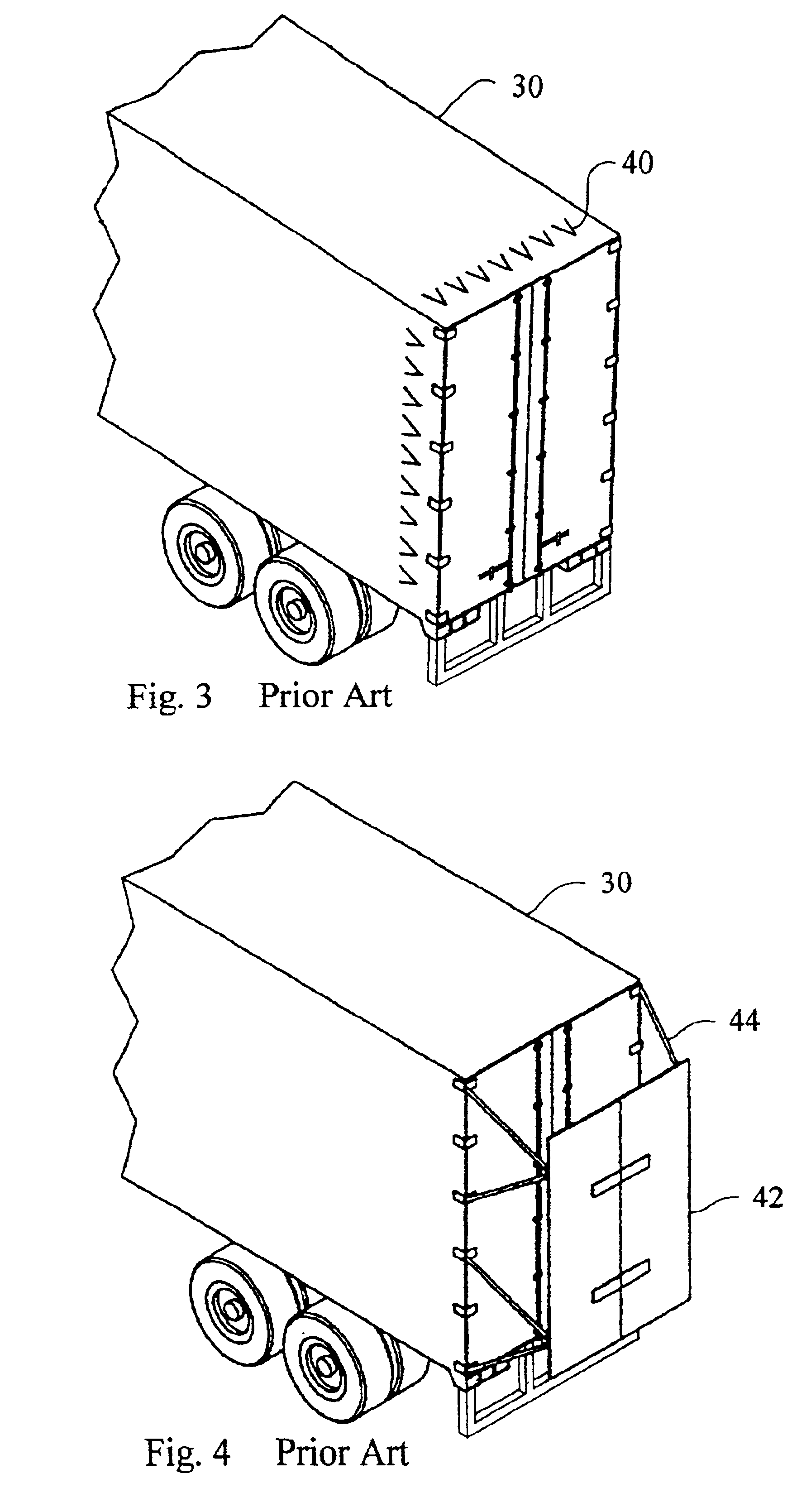
One obvious
disadvantage of guide vanes is that they must be positioned at the trailing edges of the bluff body, where they will impede the opening of rear swinging
doors on a
truck, and right where they are most likely to be damaged.
In addition, flexible guide vanes as disclosed by Rinard will likely be subject to rapid
wear and tear as they are compressed against the truck body each time the doors are opened.
Also, the guide vanes at the top and bottom edges of the base surface will still be in the way whenever a large truck with rear doors is backed up against a loading dock, and they too will likely be subject to rapid wear and tear.
Early researchers had serious doubts that vortex generators could be used to produce any net drag reduction.
U.S. Pat. No. 4,455,045 issued to Wheeler in 1984 discloses
cascade type vortex generators which are expensive to manufacture and cover a relatively large surface area.
Several researchers including Thomas Morel, have reported a critical angle for rear windows of cars at roughly 30 degrees from the horizontal, which produces a sudden peak of base drag.
To the contrary, several researchers have reported finding a critical
radius of rounded trailing edges, which can produce a localized high suction coefficient for a
short distance before attached flow separates from the curved surface, which therefore increases base drag.
The primary
disadvantage of the invention in the Harris patent is the complex geometric shapes, which must be expensive to produce.
Also, the Harris patent does not report the base drag savings achieved, which suggests the drag savings are probably modest at best.
All of these active methods have significant disadvantages.
None of them can easily be added to existing vehicles.
Therefore, these methods appear to be impractical and uneconomical for use on highway vehicles in the near future.
However, there have apparently been few attempts to develop workable combinations, and the few attempts reported have apparently met with only limited success.
However it does not teach or suggest that the addition of vortex generators can produce significant additional drag reduction compared to the best configurations used without vortex generators (config.
However, this combination has not achieved widespread use.
This may have been in part because he did not have access to the more effective vortex generators now available.
Mair was also reported to have tried using vortex generators in combination with a trailing disc to reduce the base drag of an axisymetric bluff body, but found no beneficial results.
To the contrary, he reported testing such a combination in a wind tunnel and reported finding that no additional drag reduction was obtained.
In summary, none of the inventions disclosed in prior art provides sufficient base drag reduction, with acceptable added vehicle lengths and other costs, to achieve widespread use on highway vehicles.

