Vehicle braking apparatus

a technology for braking apparatus and vehicles, which is applied in the direction of braking components, propulsion using engine-driven generators, electric devices, etc., can solve the problems of energy loss from battery charging and discharging, inability to use regenerated electric power for braking, and need for a larger battery to offset those energy losses. , to achieve the effect of reducing the size of the battery

Inactive Publication Date: 2005-11-01
NISSAN MOTOR CO LTD
View PDF11 Cites 44 Cited by
  • Summary
  • Abstract
  • Description
  • Claims
  • Application Information

AI Technical Summary

Benefits of technology

[0009]Accordingly, to advantageously solve the abovementioned problems, and from the perspective of taking measures for the environment and fuel economy, an object of the prese

Problems solved by technology

It has been discovered that in the abovementioned conventional vehicle braking apparatus that uses regenerative braking in parallel with hydraulic braking, that the regenerated electric power cannot be used for braki

Method used


Image

  • Vehicle braking apparatus
  • Vehicle braking apparatus
  • Vehicle braking apparatus

Examples


second embodiment

[0053]Referring now to FIGS. 3 and 4, a vehicle braking apparatus 21 in accordance with a second embodiment will now be explained. In view of the similarity between the first and second embodiments, the parts of the second embodiment that are identical to the parts of the first embodiment will be given the same reference numerals as the parts of the first embodiment. Thus, the descriptions of the parts of the second embodiment that are identical to the parts of the first embodiment may be omitted for the sake of brevity.

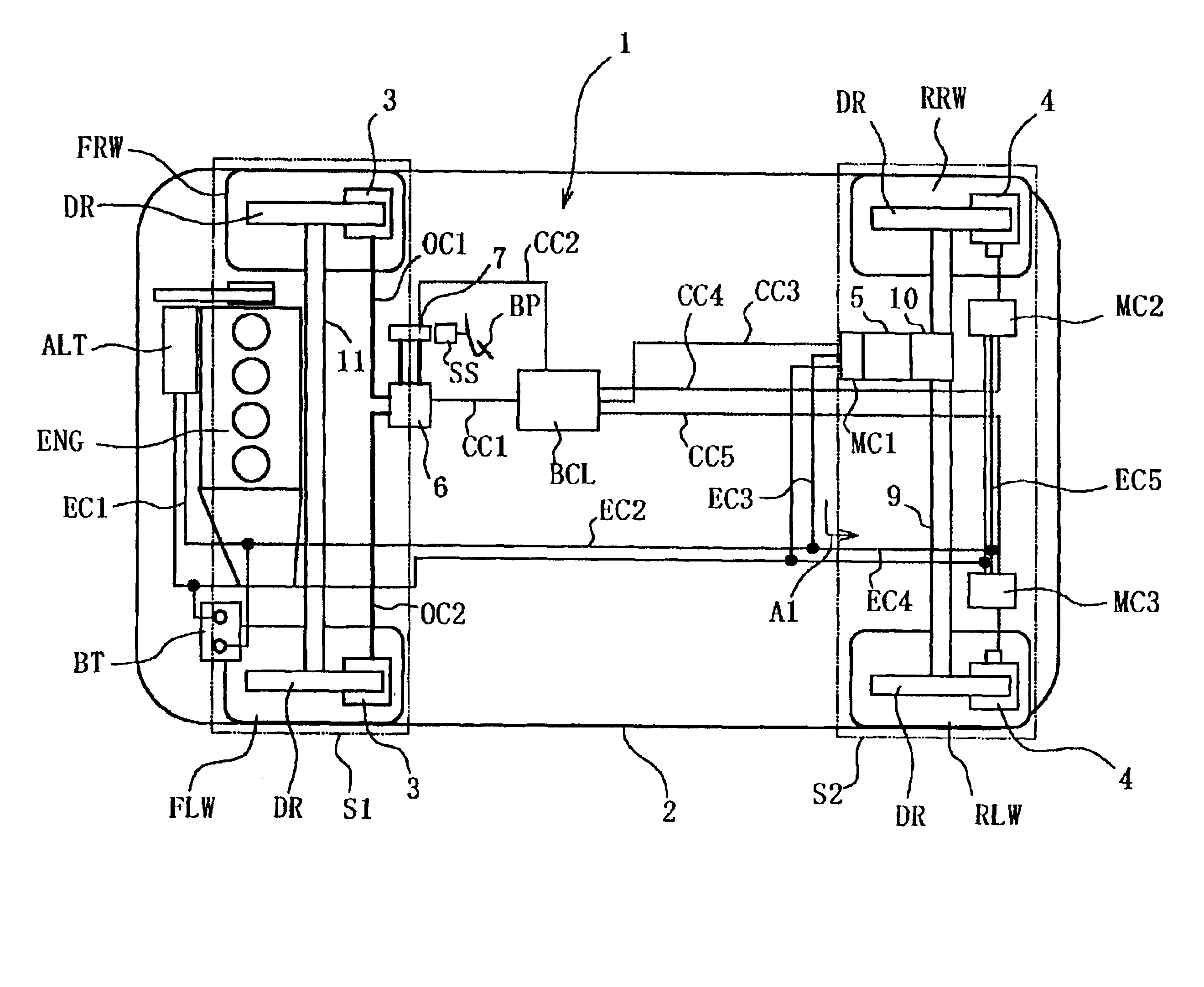
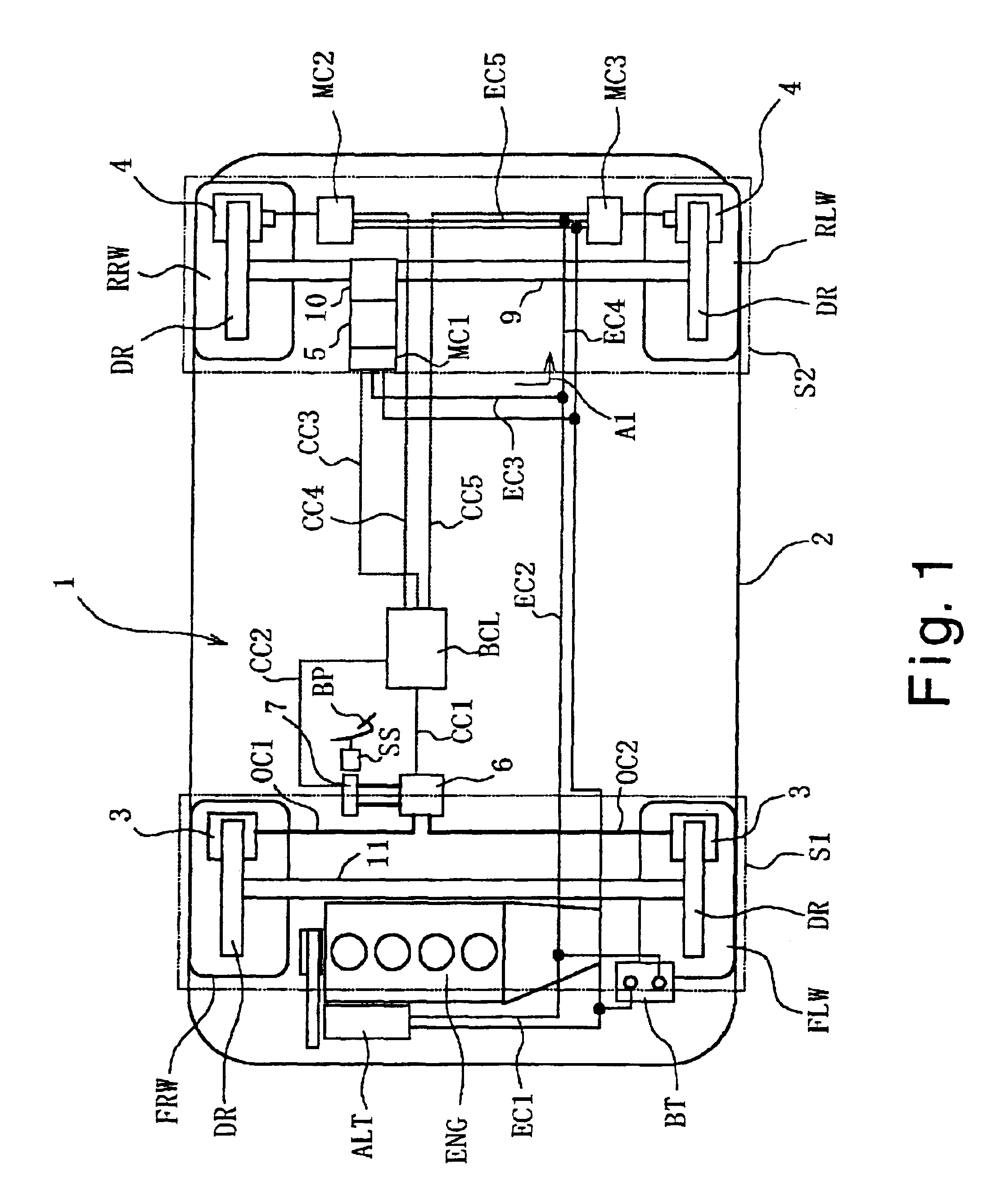
[0054]FIG. 3 is a system block diagram that shows the motor vehicle braking apparatus 21 according to the second embodiment of the vehicle braking apparatus of the present invention. The motor vehicle braking apparatus 1 of the first embodiment is constituted so that a single regenerative brake 5 in common with the right and left rear wheels RRW and RLW is linked to the differential gear 10. However, the motor vehicle braking apparatus 21 of the second embodiment is ...

third embodiment

[0061]Referring now to FIG. 5, a vehicle braking apparatus 31 in accordance with a third embodiment will now be explained. In view of the similarity between the third embodiment and the prior embodiments, the parts of the third embodiment that are identical to the parts of the prior embodiments will be given the same reference numerals as the parts of the prior embodiments. Moreover, the descriptions of the parts of the third embodiment that are identical to the parts of the prior embodiments may be omitted for the sake of brevity.

[0062]FIG. 5 is a system block diagram that shows the motor vehicle braking apparatus 31 according to the third embodiment of the vehicle braking apparatus of the present invention. The motor vehicle braking apparatus 31 of the present third embodiment includes all of the features of the motor vehicle braking apparatus 1 of the first embodiment, except that the single regenerative brake 5 has been replaced with a rear regenerative brake 5a and a front a re...

fourth embodiment

[0072]Referring now to FIG. 6, a vehicle braking apparatus 41 in accordance with a fourth embodiment will now be explained. In view of the similarity between the fourth embodiment and the prior embodiments, the parts of the fourth embodiment that are identical to the parts of the prior embodiments will be given the same reference numerals as the parts of the prior embodiments. Moreover, the descriptions of the parts of the fourth embodiment that are identical to the parts of the prior embodiments may be omitted for the sake of brevity.

[0073]FIG. 6 is a system block diagram that shows the motor vehicle braking apparatus 41 according to the fourth embodiment of the vehicle braking apparatus of the present invention. The motor vehicle braking apparatus 41 of the present embodiment is similar to the motor vehicle braking apparatus 21 of the previous second embodiment shown in FIG. 3, except that the regenerative brakes 5 has been replaced with a pair of rear regenerative brakes 5a and a...


PUM


Abstract

A vehicle braking apparatus is provided that basically comprises a hydraulic braking apparatus, an electric braking apparatus and a regenerative braking apparatus. The hydraulic braking apparatus is configured and arranged to apply a hydraulic braking force on at least one first wheel subject to a first braking system. The electric braking apparatus is configured and arranged to apply an electric braking force on at least one second wheel subject to a second braking system that is different from the first braking system. The regenerative braking apparatus is configured and arranged to apply a regenerative braking force on one of the first and second wheels subject to a corresponding one of the first and second braking systems. The vehicle braking apparatus enables the battery for an electric braking apparatus to be more compact while also enabling regenerated electric power to be used for braking.

Description

BACKGROUND OF THE INVENTION[0001]1. Field of the Invention[0002]The present invention generally relates to a vehicle braking apparatus that applies a braking force to the wheels of a vehicle.[0003]2. Background Information[0004]An example of a conventional vehicle braking apparatus is disclosed in Japanese Laid-Open Patent Application No. 05-161211 that uses two different types of braking devices for an electric vehicle. In particular, this publication discloses using a hydraulic brake apparatus having four hydraulic braking devices to apply a braking force to each of the wheels of the vehicle and an electric drive motor that acts as a regenerative brake apparatus to apply a braking force to the rear wheels of the vehicle. In this conventional vehicle braking apparatus, a controller selectively operates the hydraulic brake devices and the regenerative braking of the electric drive motor in depending on operating conditions. Thus, the hydraulic brake apparatus selectively operates on...

Claims


Application Information

Patent Timeline
IPC IPC(8): B60K6/04B60L7/24B60L7/00B60K6/00B60T13/58B60T13/10B60T8/26B60T8/00B60K1/02B60K1/00B60K17/356B60K17/34B60T8/17
CPCB60K6/52B60L7/24B60T1/10B60T8/00B60T8/267B60T13/586B60W10/08B60W10/184B60L3/0076B60L7/14B60L11/123B60L11/14B60L15/2009B60K6/48B60K1/02Y02T10/642B60K17/356B60T2270/602B60T2270/603B60T2270/608B60T2270/613B60W20/00Y02T10/6221Y02T10/6265B60L2210/40B60L2220/46B60L2240/12B60L2240/421B60L2240/423Y02T10/7077Y02T10/7005Y02T10/7241Y02T10/7275Y02T10/6217B60L50/16B60L50/61Y02T10/62Y02T10/64Y02T10/70Y02T10/7072Y02T10/72B60W10/18B60W30/18127B60W2510/18B60W20/13
Inventor TSUNEHARA, HIROSHI
Owner NISSAN MOTOR CO LTD
Why Eureka
Try Eureka