Polarized light emitting device for illuminating a display
- Summary
- Abstract
- Description
- Claims
- Application Information
AI Technical Summary
Benefits of technology
Problems solved by technology
Method used
Image

Examples
first embodiment
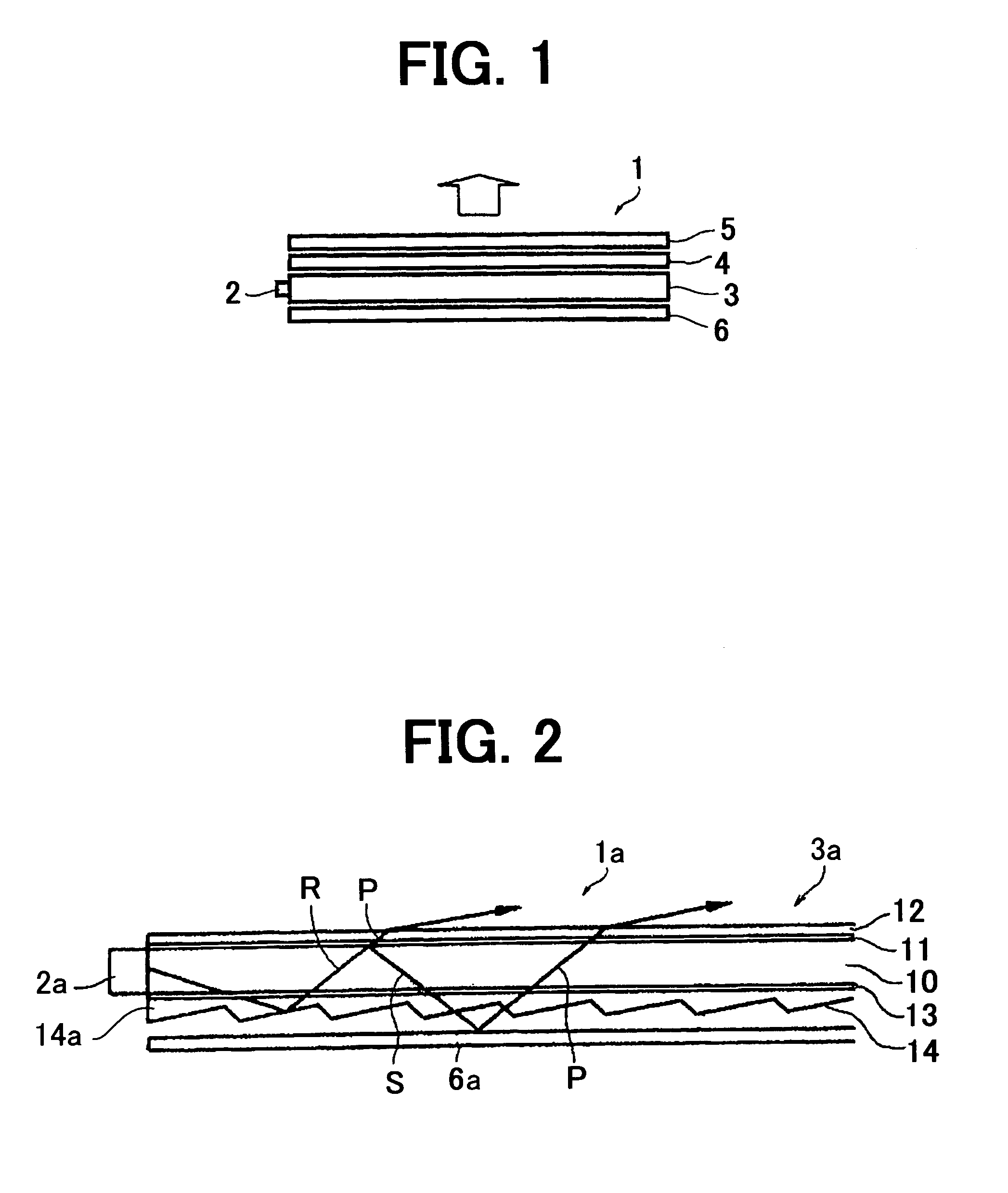
[0017]FIG. 1 is a side view showing a generally-used-lighting-device structure, just a reference for the present invention, and FIG. 2 is a side view of a lighting device according to the present invention.
[0018]Referring to FIG. 1, a lighting device 1 comprises an LED 2 as a light source, a light guide plate 3 corresponding to the LED 2, a prism sheet 4 disposed above the light guide plate 3 for arranging the light discharged from an upper discharge surface of the light guide plate 3, a diffusion sheet 5, and a reflection plate 6 disposed under the light guide plate 3. Light is discharged from the diffusion sheet 5 in the direction shown by the arrow so as to illuminate the LCD (not shown).
[0019]The present invention is to improve the light guide plate 3. Light discharged from the upper surface of the light guide plate 3 is separated to split P-polarization components and S-polarization components, and one of the P-polarization components and S-polarization components is used for i...
second embodiment
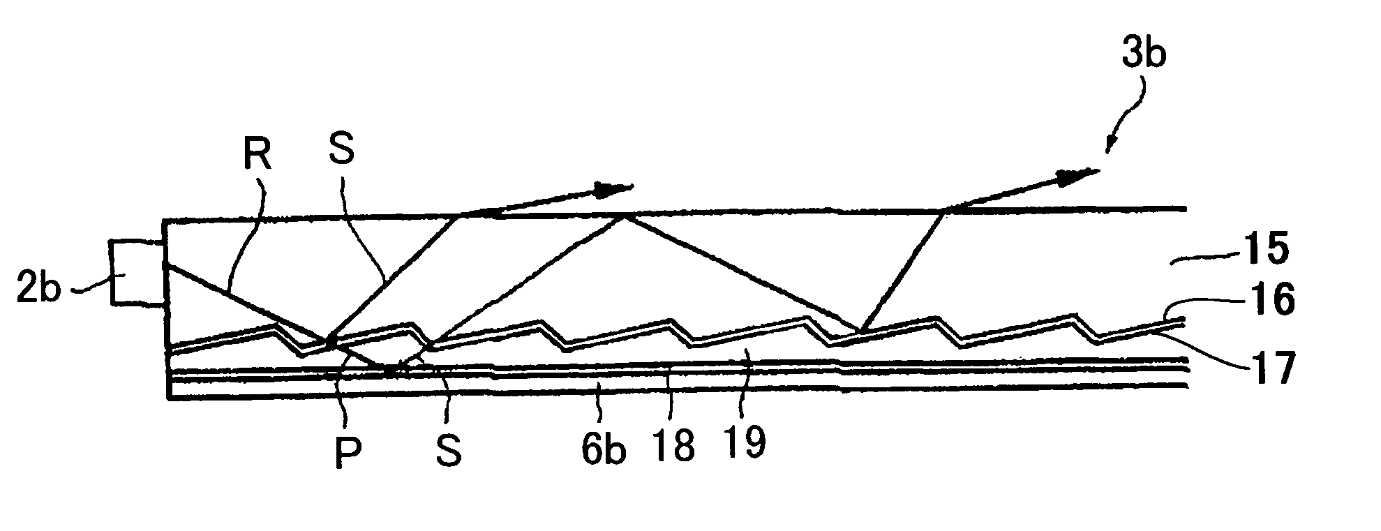
[0029]FIG. 3 is a side view of the present invention. A light guide plate 3b comprises a light guide body 15, prisms 16 formed on the lower surface of the light guide body 15, a polarization split film 17 formed on the underside of the prisms 16, an intermediate member 19 on the underside of the polarization split film 17, and a polarizing-direction modifier 18 formed on the underside of the intermediate member 19. Thus, the prisms 16, polarization split film 17, intermediate member 19, and polarizing-direction modifier 18 are integrated with the light guide body 15. Here, a reflection plate 6b is secured to the polarizing-direction modifier 18.
[0030]It is clear that the reflection plate 6b can be formed integral with the light guide plate 3b.
[0031]The light P of P-polarization component in the light R emitted from the light source such as an LED 2b transmits the polarization split film 17, and the light S of S-polarization component is reflected by the film 17. The light S reflect...
third embodiment
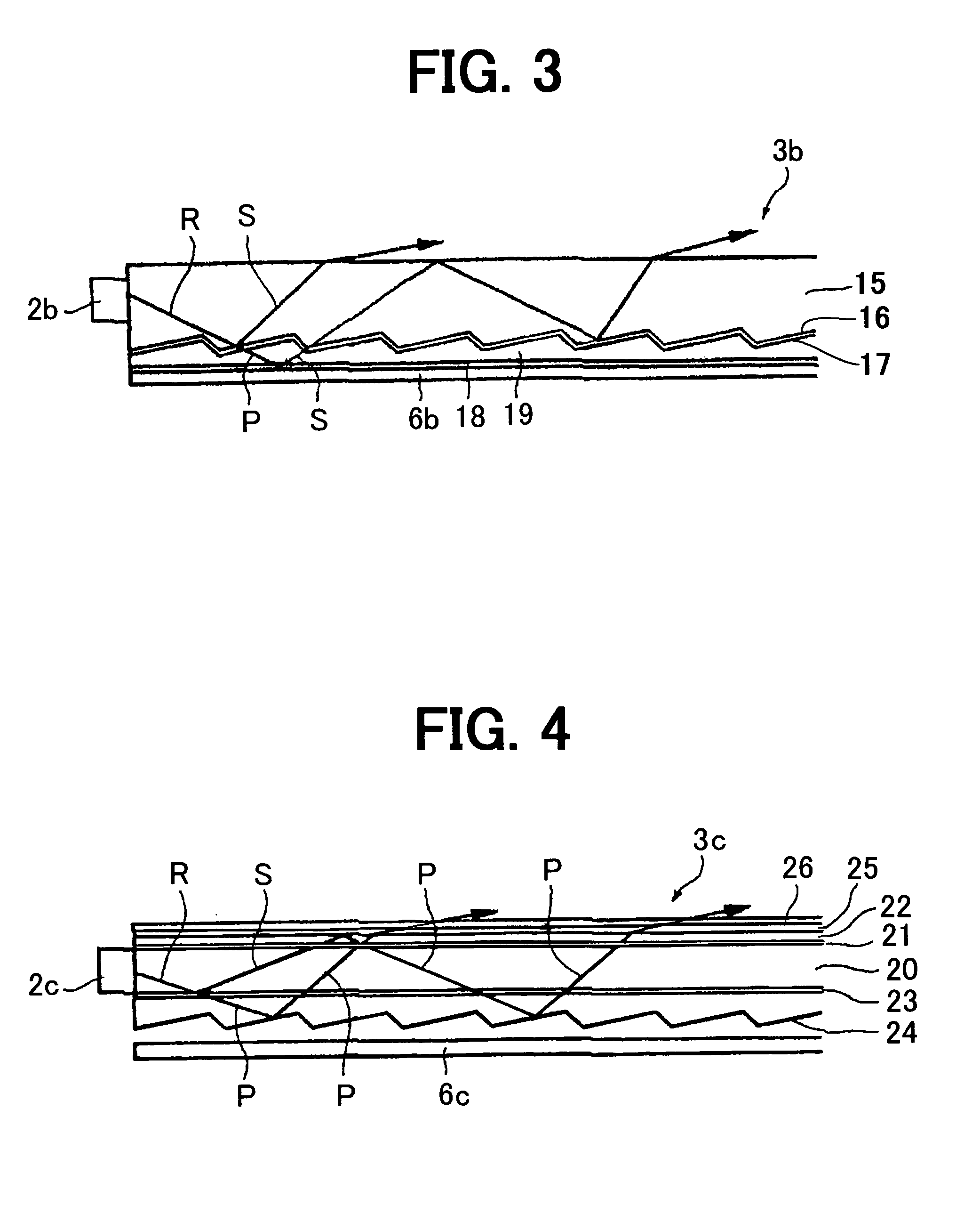
[0033]FIG. 4 is a side view of the present invention. A light guide plate 3c comprises a light guide body 20, a first polarizing-direction modifier 21 on the upper surface of the light guide body 20, a first cover 22 on the first polarizing-direction modifier 21, a second polarizing-direction modifier 25 on the first cover 22, a second cover 26 on the modifier 25, a polarization split film 23 on the underside of the light guide body 20, and prisms 24 on the underside of the polarization split film 23.
[0034]In the light guide plate 3c, the light R from the an LED 2c is separated to the light P and the light S by the polarization split film 23, the light P transmits the polarization split film 23, and the light S is reflected by the film. The reflected light S transmits the polarizing-direction modifier 21, thereby being changed to a circular polarization light. The circular polarization light is reflected by the upper surface of the first cover 22 because of large incident angle, and...
PUM
 Abstract
Description
Claims
Application Information
 - R&D
- Intellectual Property
- Life Sciences
- Materials
- Tech Scout
- Unparalleled Data Quality
- Higher Quality Content
- 60% Fewer Hallucinations
Browse by: Latest US Patents, China's latest patents, Technical Efficacy Thesaurus, Application Domain, Technology Topic, Popular Technical Reports.
© 2025 PatSnap. All rights reserved.Legal|Privacy policy|Modern Slavery Act Transparency Statement|Sitemap|About US| Contact US: help@patsnap.com